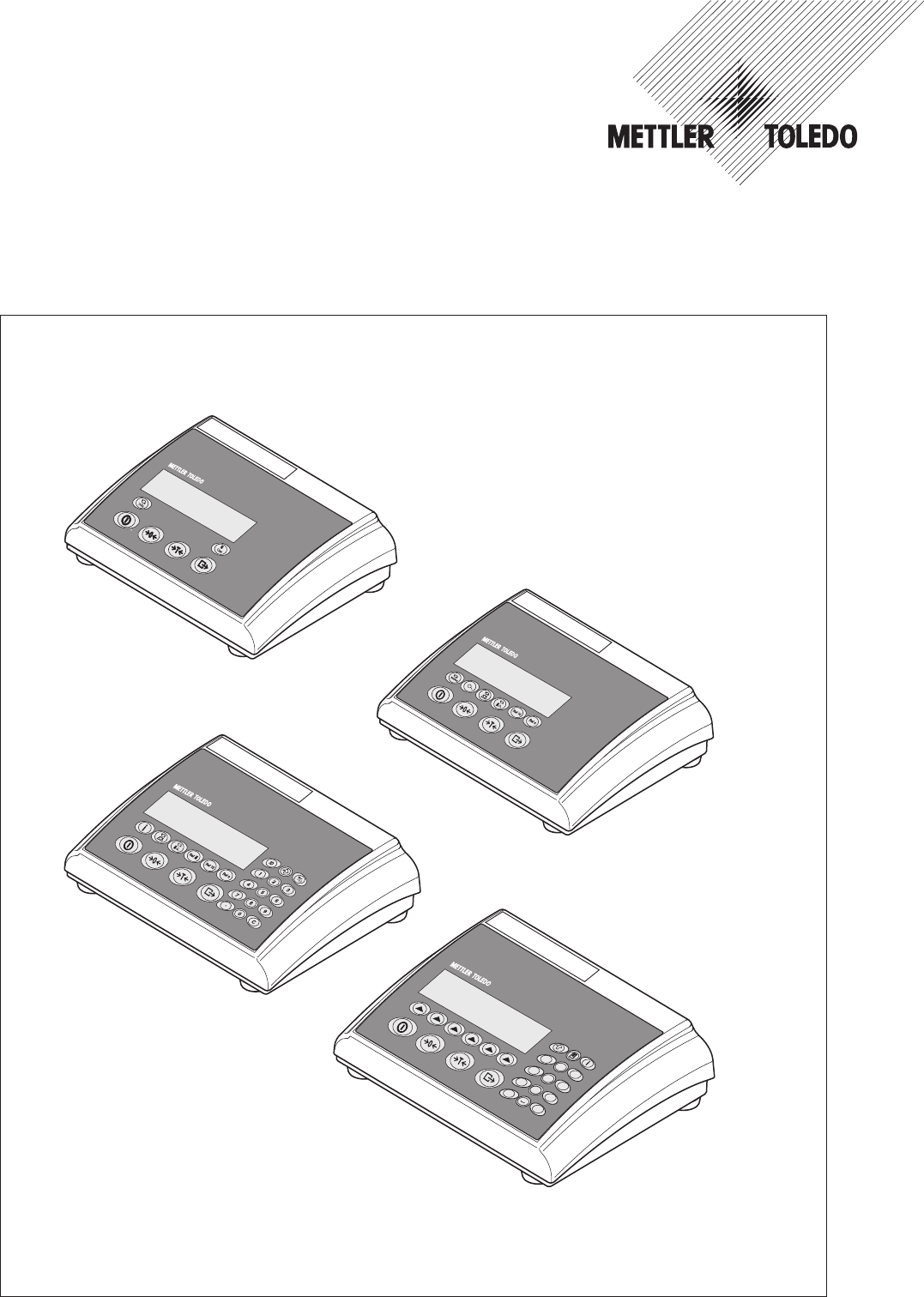
Installation information METTLER TOLEDO IND425 / IND435 / IND445 / IND465 terminals -, 1 /& ab 4 gh pq i jk 7 rs tu . + ... 2 c 3 de 5 l f 6 mn 8 o v wx 0 9 yz C www.mt.
Contents 1 Important information ...................................................................................................................................4 1.1 1.2 1.3 Product range ................................................................................................................................................4 Documentation ..............................................................................................................................................
Chapter 1: Important information 4 1 Important information Please read this installation information carefully and observe all instructions! Please contact the Sales Office if there are items which are missing or have been wrongly delivered, or if you encounter any other problems with the terminal. These instructions are intended for those who have a basic but adequate knowledge of the design of weighing systems. 1.1 Product range The OptionPac is a special equipment for the IND4... terminals.
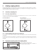
Chapter 2: Attaching weighing platforms 5 2 Attaching weighing platforms All analog weighing platforms can be attached to IND4.. terminals if they are conform to the required specifications (see chapter 5). Two different weighing platforms can be attached if the terminal also has an OptionPac with an analog option. Compact two-scale systems can therefore be constructed using just one terminal. 2.1 Instructions on weighing cells 2.1.
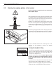
Chapter 2: Attaching weighing platforms 6 2.3 Attaching the weighing platform to the terminal Before assembling, the terminal must first be disconnected from the power supply! Undo the gland nut of the heavy gauge cable gland and remove this together with the black crimping ferrule and the two washers. Undo the rear cover plate of the terminal (6 Torx T20 screws) and fold down carefully (cable connections!).
Chapter 2: Attaching weighing platforms 7 2.4 Connection of a second weighing platform to the analog option The analog option, which allows the connection of a second weighing platform, is housed in the OptionPac. The connection of a second weighing platform to the analog option requires that a weighing platform already be connected to the terminal. The analog second weighing platform is connected directly to the OptionPac via a 9-pin Sub-D connector.
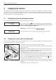
Chapter 3: Configuring the terminal 8 3 Configuring the terminal The configuration data of the weighing system must be known before the terminal can be configured (see chapter 5). The IND4.. terminal has a service level for entering configuration data as well as for calibrating and linearization of the weighing system. This level is protected by a password. The menus of the service level are used in exactly the same way as those for the operator and for the supervisor (see operating instructions). 3.
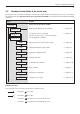
Chapter 3: Configuring the terminal 9 3.3 Summary of menu blocks of the service level The complete menu is available including those menu blocks to which operators and supervisors have access. The following summary shows only those menu blocks of the service level in the menu “SCALE”. The rest of the menu is described in the operating instructions. Display Remarks Service level in menu block “SCALE”: SCALE Determining the admissibility for certification ––> chapter 3.
Chapter 3: Configuring the terminal 10 Admissibility for certification (SCALE –> Metrology ) 3.4 Display Remarks Setting the admissibility for certification: ▼ MEtROLO NO APPr ▼ ▼ ▼ OIML ▼ Scale not certifiable. Scale certifiable to OIML. Caution: When a scale is declared certifiable, then certain settings are no longer available. Direct access to the menu for the service technician is also blocked (see chapter 3.2)! Selecting the scale to be configured (SCALE –> Scale 1) 3.
Chapter 3: Configuring the terminal 11 Entering the configuration data (SCALE –> Scale Build) 3.8 Display Remarks Entering configuration data RESOL. ▼ SCL.CAP ––> chapter 3.8.1 ▼ bAS.UNIt Defining the type of scale Specifying the basic units ––> chapter 3.8.2 ▼ SCAL.tYP Specifying the capacity of the weighing system ––> chapter 3.8.3 ▼ ▼ SCAL.bLd Selecting the resolution ––> chapter 3.8.4 ▼ ▼ Defining the type of scale (SCALE –> Scale Build –> Scale Type ) 3.8.
Chapter 3: Configuring the terminal 12 Setting the scale capacity (SCALE –> Scale Build –> Scale Capacity) 3.8.3 Display Remarks Entering the scale capacity (in the preset basic unit). ▼ SCL.CAP For IND445 / 465 terminals, the capacity can be entered via the numeric keyboard. 000015.0kg For IND425 / 435 terminals, press the ▼ be changed using the T and T key. The first digit flashes and can now keys. Confirm the new digit with the key.
Chapter 3: Configuring the terminal 13 3.10 Linearization with calibration (SCALE –> Lin-Cal ) Display Remarks Linearizing the scale system with simultaneous calibration. Calibration is carried out purely theoretically to compensate for shifts in the full load when linearizing. The loads applied are checked (±5%) and thus a basic calibration must first be carried out (chapter 3.11).
Chapter 3: Configuring the terminal 14 3.11 Basic calibration (SCALE –> Cal ) Display Remarks The basic calibration corresponds to the calibration function for the user (however, the user cannot set the preload). ▼ CAL Apply the preload and confirm with the PRELOAd key. If a test weight is already on the scale, the preload measurement can be skipped by pressing the T key. The existing zero point is then used as the reference point.
Chapter 3: Configuring the terminal 15 3.13.1 Setting the zero capturing range (SCALE –> Zero –> Zero Capture ) Display Remarks Setting the zero capturing range (when switching on and via the ▼ Z - CAPt - 2 18 ▼ ▼ Zero capturing range –2% to +18% Zero capturing range –2% to +2% (mainly for certifiable scales) 2 ▼ -2 key). ▼ The zero capturing range is set at the expense of the nominal capacity of the scale.
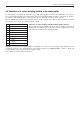
Chapter 4: Table of Geo values 16 4 Table of Geo values Height above sea level in meters Northern or southern 0 325 650 975 1300 1625 1950 2275 2600 2925 3250 325 650 975 1300 1625 1950 2275 2600 2925 3250 3575 geographical latitude in degrees and minutes 0° 0' 5° 46' 9° 52' 12°44' 15° 6' 17°10' 19° 2' 20°45' 22°22' 23°54' 25°21' 26°45' 28° 6' 29°25' 30°41' 31°56' 33° 9' 34°21' 35°31' 36°41' 37°50' 38°58' 40° 5' 41°12' 42°19' 43°26' 44°32' 45°38' 46°45' 47°51' 48°58' 50° 6' 51°13'
Chapter 5: Setting up a weighing system and technical data 17 5 Setting up a weighing system and technical data Before setting up a weighing system with the IND4.. terminal, its basic data must first be determined. These data are to be entered into the service level of the menu (chapter 3). The typical procedure for setting up a scale system is shown below as follows. 5.
Chapter 5: Setting up a weighing system and technical data 18 How do I set up my scale? Application: Scale parameters: – simple weighing – > IND425 – heaviest weight? – simple counting – > IND435 – weight of pan holder? – convenient ct.
Chapter 5: Setting up a weighing system and technical data 19 5.2 Measuring ranges of the IND4.. terminal When setting up a weighing system, consider the measuring ranges of the IND4.. terminal according to the summary given below. a: Total preload applied to weighing cell when calibrating (upper part of platform, weighing pan, roller track, etc.
Chapter 5: Setting up a weighing system and technical data 20 5.3 Technical data Only those specifications needed for using this installation information are shown below. The other technical data are given in the operating instructions. Data for the terminal Resolution 300 000 points for non-certifiable applications 7 500 points for certifiable applications Weighing ranges Up to 3 weighing ranges defined in the menu, incl. movable or fixed fine ranges.
Chapter 6: Event and error messages 21 6 Event and error messages Overload: Reduce the load on the scale or reduce the preload. Underload: Place the weighing pan on the scale and ensure it can move freely. Result not stable: Always appears when not stable (when zeroing, taring, etc.). If the scale still does not become stable after a long time, check the environmental conditions. If necessary, change the setting of the vibration adapter or use the dynamic weighing function.
12234456781 22011473B Subject to technical changes © Mettler-Toledo (Albstadt) GmbH 05/08 Mettler-Toledo (Albstadt) GmbH D-72458 Albstadt Tel. ++49-7431-14 0, Fax ++49-7431-14 232 Internet: http://www.mt.