
Technical data

Chapter 2: Installation
Electrical Connections
(9/00) 2-19
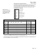
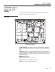
Optional Multifunction I/O
PCB Serial and Discrete
Connections
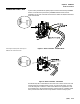
This section gives proper cable connections to COM 3, COM 4, PAR 3, AND PAR 4,
which are located on the optional Multifunction I/O PCB.
RXD
DCD
TXD
DTR
GND
CTS
RTS
DSR
COM 3 COM 4
RI
TXD
RXD
GND
RXD+
TXD-
TXD+
RXD-
+V
8
7
6
5
4
3
2
1
GND
1
2
3
4
5
6
7
8
+VOUT
IN OUT
MULTIFUNC
T
PAR 3 PAR 4
METTLER TOLEDO
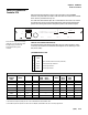
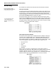
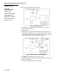
COM3 Interconnect Wiring
COM3 supplies all inputs and outputs to allow full handshaking and modem interfacing.
The COM3 port is only available with the optional Multifunction PCB. When interfacing
COM3 to devices other than those listed for COM2 RS-232, refer to the documentation
for the particular device for handshaking needs and suggested wiring.
The following general interconnect options are offered for the 9 and 25 pin connectors.
COM3 With Full Handshaking
COM3 DB25 DB9 DCE
DCD
RXD 2 2** **This connection is only required for devices that
input data to the JAGXTREME terminal, such as
devices that send ASCII “C, T, P, Z, or U”.
TXD 3 3
DTR 6 6
GND 7 5
DSR 20 4
RTS 5 8
CTS 4 7
RI
COM4 Interconnect Wiring
The wiring instructions for the COM2 serial port apply to COM4 on the Multifunction PCB.
Refer to the section presented earlier in this chapter entitled COM2/COM4 RS-232
(Controller PCB Serial Port) to interface COM4 to DigiTOL scales and printers.
PAR 3 Discrete Input Port
Each of the eight PAR 3 inputs can be configured for different remote inputs including
input from the JAGXTREME keypad (Tare, Clear, Zero, Select, Escape, and Enter). PAR 3
inputs can also be configured for remote print, unit switching, alternate scale selection,
or template selection. Polarity (switch to ground or open a ground connection to initiate
remote input) can also be selected. Refer to Chapter 3.
The wiring instructions for the PAR 1 discrete inputs apply to PAR 3 on the Multifunction
PCB. Refer to the section entitled PAR 1 Input Connections for wiring details.