
Technical data


METTLER TOLEDO JAGXTREME Terminal Technical Manual
(9/00) 2-26
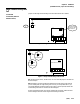
Multifunction I/O PCB
Jumpers on the Multifunction I/O PCB should be set as shown below:
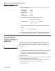
Figure 2-s: Multifunction I/O PCB
W1— must be set for the desired voltage that the selected PAR 3 and PAR 4 parallel outputs will
be referenced to through 10 K ohm pull-up resistors resident on the Multifunction PCB. It is also
the voltage that will be present on the V OUT terminal of PAR 3. The choices are +5 VDC, +12
VDC, and +20 VDC.
W2— selects the voltage that will be present at the +V terminal of the COM4 Port. The choices are
+5 VDC, +12 VDC, and +20 VDC. Select +20 VDC when connecting a DigiTOL scale base to
COM4.
W3— ON, test (unused)
W4— OFF
W5— ON, test (unused)
W6— IRQ 4
W7— ON
W8— ON
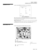
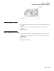
Installing Options
JAGXTREME terminals may be ordered with options already installed at the factory.
Options may also be ordered separately and installed in the field. Remember when
installing options that the Controller PCB must always be in the top slot. The remaining
slots are for optional boards and can be used interchangeably.
Figure 2-t: JAGXTREME Terminal Option Panel Slots
CAUTION
OBSERVE PRECAUTIONS FOR HANDLING ELECTROSTATIC DEVICES.