
Specifications

Chapter 14: Appendices
Appendix 11: Engineering Specifications
(12/99) 14-49
4
Load Cell Specifications
4.1
All load cells shall meet or exceed the National Institute of Standards
and Technology (NIST) Handbook 44 for Class III weighing devices
and shall be certified by the National Type Evaluation Program
(NTEP) for 5,000 division Class III accuracy.
4.2
All load cells shall be certified to meet or exceed Organisation de
Metrologie Legale (OIML) C3 R60 3,000 division accuracy
requirements.
4.3
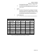
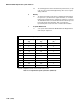
Load cells shall have the following individual characteristics:
4.3.1
Rated Capacity (R.C.): ____________
4.3.2
Rated Output: ____________
4.3.3
Zero Balance: ____________
4.3.4
Combined Error Due To
Non-Linearity & Hysteresis: ____________
4.3.5
Non-Repeatability: ____________
4.3.6
Temperature Compensation: ____________
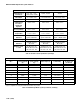
4.3.7
Terminal Resistance
Input: ____________
Signal: ____________
4.3.8
Excitation Voltage: ____________
4.3.9
Insulation Resistance: ____________
4.3.10
Maximum Loads
Safe Overload: 150% of R.C.
Ultimate Overload: 300% of R.C.
Safe Side Load: 100% of R.C.
4.4
Each load cell shall have a hermetically sealed strain gauge cavity.
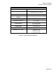
4.5
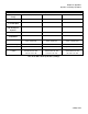
Each load cell shall have a data plate affixed to the load cell which
clearly shows:
4.5.1
Manufacturer
4.5.2
Capacity
4.5.3
Part Number
4.5.4
Serial Number
4.5.5
Class Number
4.5.6
NTEP Certificate of Conformance Number
4.5.7
Maximum Divisions (Nmax)
4.5.8
Load Cell Vmin
4.6
Load cells shall be mounted to the base plate with stainless steel
socket head cap screws.
5
Junction Box Specifications
5.1
Junction box enclosure shall be constructed of type 304 stainless
steel and shall be designed to NEMA 4X/IP65 standards.
5.2
The junction box enclosure shall have washdown duty connectors,
one for each load cell cable, and one additional connector for the
instrument cable. Multiple cables using single box connectors are not
acceptable.
5.3
The junction box shall contain a printed circuit board for the purpose
of individual load cell wiring termination, summing of the output
signals from each load cell, trimming/balancing the load cell signals,
and wiring the interface to the digital instrument.
5.4
The printed circuit board shall have individual connectors for each of
the load cells, and the instrument interface cable. Each wire shall
have a single terminal connection. Doubling up or ganging of wires
to one terminal is not acceptable.