
Specifications

Chapter 5: General Installation Guidelines
Electrical Wiring
(12/99)
5-21
Electrical Wiring
A weigh module system requires two types of electrical cables:
• Load cell cables to connect each load cell to a junction box
(cables are usually supplied with the load cells).
• A home run cable to connect the junction box to an indicator.
Load Cell Cables
Each load cell is connected by cable to a junction box, which adds the individual
load cell signals together to provide one signal that can be transmitted to the
indicator. METTLER TOLEDO uses three different operating modes: analog, DigiTOL,
and IDNet. For each of these operating modes, the junction box design and wiring
is different.
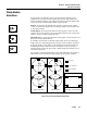
Analog Systems
Most weighing systems use an analog junction box, which requires an analog-
compatible indicator. An analog junction box can sum up to four load cells. For
weigh module systems with more than four load cells, you will need to connect
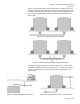
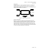
several junction boxes together. Sample layouts for analog systems with four and
six load cells are shown in Figure 5-26. The maximum number of load cells in a
weighing system depends on the indicator’s power supply and the load cell bridge
resistance. For analog junction box dimensions and wiring details, see Appendix
9.
Figure 5-26: Analog Junction Box Layouts
To Indicator
To Indicator