Operation Manual Transmitter M300 FLOW Transmitter M300 FLOW 52 121 319
Transmitter M300 FLOW © 09 / 08 Mettler-Toledo AG, CH-8606 Greifensee, Switzerland Printed in Switzerland Transmitter M300 FLOW 52 121 319
Transmitter M300 FLOW Operation Manual Transmitter M300 FLOW © 09 / 08 Mettler-Toledo AG, CH-8606 Greifensee, Switzerland Printed in Switzerland Transmitter M300 FLOW 52 121 319
Transmitter M300 FLOW Content 1 Introduction_ ___________________________________________________________________________________________ 7 2 Safety instructions_______________________________________________________________________________________ 7 2.1 Definition of equipment and documentation symbols and designations_________________________________________ 7 2.
Transmitter M300 FLOW 8 Configuration__________________________________________________________________________________________ 35 8.1 Enter Configuration Mode___________________________________________________________________________ 35 8.2 Measurement Setup_ ______________________________________________________________________________ 36 8.2.1 Set Averaging_____________________________________________________________________________ 37 8.2.
Transmitter M300 FLOW 14 Trouble Shooting_ ______________________________________________________________________________________ 63 14.1 Changing the Fuse________________________________________________________________________________ 63 15 Accessories and Spare Parts______________________________________________________________________________ 63 16 Specifications__________________________________________________________________________________________ 64 16.
Transmitter M300 FLOW 1 Introduction Statement of Intended Use – The M300 Flow transmitter is a single- or four- channel online process instrument for measuring conductivity or resistivity of fluids. It will interface with a variety of different Mettler-Toledo sensors, which connect to the transmitter using cables of varied lengths. A large four line backlit Liquid Crystal Display conveys measuring data and setup information.
Transmitter M300 FLOW The following is a list of general safety instructions and warnings. Failure to adhere to these instructions can result in damage to the equipment and/or personal injury to the operator. – The M300 Transmitter should be installed and operated only by personnel familiar with the transmitter and who are qualified for such work. – The M300 Transmitter must only be operated under the specified operating conditions (see section 16).
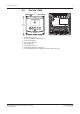
Transmitter M300 FLOW 3 Unit overview M300 models are available in both a 1/4DIN and 1/2DIN case size. The 1/4DIN is a panel-mount only design and the 1/2DIN models provides an integral P65 housing for wall-, or pipe-mount. 3.1 Overview 1/4DIN 4.01 [102] 1 8 4 5 7 6 4.
Transmitter M300 FLOW 3.2 10 Overview 1/2DIN 5.90 [150] 1 5 M300 3 5.
Transmitter M300 FLOW 11 3.3 Control/Navigation Keys 3.3.
Transmitter M300 FLOW 3.3.2 12 Navigation keys ESC Menu 3.3.2.1 Cal Info Enter Navigating the menu tree Enter the desired main Menu branch with the , or keys. Use the and keys to navigate through the selected Menu branch. C NOTE: In order to back up one menu page, without escaping to the measurement mode, move the cursor under the UP Arrow character at the bottom right of the display screen and press [Enter]. 3.3.2.
Transmitter M300 FLOW 3.3.5 13 Navigation with ↑ in Display If a ↑ is displayed on the bottom right hand corner of the display, you can use the or the key to navigate to it. If you click [ENTER] you will navigate backwards through the menu (go back one screen). This can be a very useful option to move back up the menu tree without having to exit into the measuring mode and re-enter the menu. 3.3.
Transmitter M300 FLOW 4 Installation instruction 4.1 Unpacking and inspection of equipment 14 Inspect the shipping container. If it is damaged, contact the shipper immediately for instructions. Do not discard the box. If there is no apparent damage, unpack the container. Be sure all items shown on the packing list are present. If items are missing, notify Mettler-Toledo immediately 4.1.
Transmitter M300 FLOW 4.1.2 – – – – Installation procedure – 1/4DIN models Make cutout in panel (see dimensions cutout drawing). Be sure surface surrounding cutout is clean, smooth and free of burrs. Slide face gasket (supplied with transmitter) around transmitter from the back of the unit. Place transmitter into cutout hole. Be sure there are no gaps between the transmitter and panel surface.
Transmitter M300 FLOW 4.1.3 16 Panel cutout dimensional information – 1/2DIN models 1/2DIN Model transmitters are designed with an integral rear cover for stand-alone wall mount installation. The unit may also be wall mounted using the integral rear cover. See installation instructions in Section 4.1.4. Below are cut-out dimensions required by the 1/2DIN models when mounted within a flat panel or on a flat enclosure door. This surface must be flat and smooth.
Transmitter M300 FLOW 4.1.4 17 Installation procedure – 1/2DIN models For Wall Mount: – Remove rear cover from front housing. – Start by unscrewing the four screws located on the face of the transmitter, in each corner. This allows the front cover to swing away from the rear housing. – Remove the hinge-pin by squeezing the pin from each end. This allows the front housing to be removed from the rear housing – Drill out wall-mount breakthroughs in the rear housing.
Transmitter M300 FLOW 4.2 18 Connection of power supply All connections to the transmitter are made on the rear panel of all models. Be sure power to all wires is turned off before proceeding with the installation. High voltage may be present on the input power wires and relay wires. A two-terminal connector on the rear panel of all M300 models is provided for power connection. All M300 models are designed to operate from a 20–30 VDC or a 100 to 240 VAC power source.
Transmitter M300 FLOW 4.2.2 19 1/2DIN housing (wall mount) 1 2 1 Connection of power supply 2 Terminal for sensor 4.3 Connector PIN definition 4.3.1 TB1 and TB2 for 1/2DIN and 1/4DIN versions Power connections are labeled – N for Neutral and +L for Line, for 100 to 240 VAC or 20 – 30 VDC.
Transmitter M300 FLOW 4.3.2 20 TB3 and TB4 for 1/2DIN and 1/4DIN versions TB3 and TB4 are used for sensor inputs. TB3 Pin no. Transmitter TB3 Function TB4* 1 – Not used 2 GND Ground 3 BJ* DJ* +10 VDC 4 Bin* Din* Flow Pulse Input 5 +5V + 5 VDC 6 GND Ground 7 AJ CJ* + 10 VDC 8 AIn CIn* Flow Pulse Input 9 +5V + 5 VDC * Four channel models only AJ and AIN refer to connections for channel A.
Transmitter M300 FLOW 4.4 21 Connection of Sensor The M300 FLOW Transmitter is designed to operate with various types of sensors. These sensors require different wiring configurations. Listed below are instructions for wiring the various types of sensors offered by Mettler-Toledo Thornton for use with this transmitter. Please consult the factory for assistance if attempting to wire sensors not offered by Mettler-Toledo Thornton as some sensors may not be compatible. 4.
Transmitter M300 FLOW 4.7.1 22 Wiring for ”HIGH” type flow sensors The following wiring information is used when connecting (Burkert 8020 and 8030 type) inline Hall effect 5VDC, flow sensors. Thornton models 33901 thru 33935. THORNTON 33901-33935 L–, shield Pulse output L+ 10K 0.33uF Burkert 8020, 8030 Hall-Effect Sensor Type: high TB 3 1 2 GND 3 4 5 +5V 6 GND 7AJ 8 A IN 9 +5V M300 transmitter Extension cable not provided.
Transmitter M300 FLOW 23 The following wiring information is used when connecting Badger (formerly Data Industrial 4000-Series) forward-swept paddlewheel type flow sensors. Thornton models 33174 thru 33177 and 33171 and 33172. THORNTON 33174-33177, 33171, 33172 black shield red clear Badger (formerly Data Industrial 4000 Series) Flow Sensors Type: high 0.33uF TB 3 1 2 GND 3 4 5 +5V 6 GND 7AJ 8 A IN 9 +5V M300 transmitter 20 ft (6.1 m) extension cable provided with sensor.
Transmitter M300 FLOW 24 The following wiring information is used when connecting Sanitary Turbine type flow sensors. Thornton models 33336 thru 33377 (Hoffer) and 33441 thru 33450 (Sponsler). THORNTON 33336-333377 (Hoffer) black shield red white Hoffer Turbine Sensors Type: high 0.33uF TB 3 1 2 GND 3 4 5 +5V 6 GND 7AJ 8 A IN 9 +5V M300 transmitter 20 ft (6.1 m) extension cable provided with sensor.
Transmitter M300 FLOW 25 The following wiring information is used when connecting Spirax Sarco/Emco flow (formerly Fluidyne) insertion type flow sensors. Thornton models 33358 thru 33375. THORNTON 33358-33375 (–) GND 1K (+) Spirax Sarco/Emco flow (formerly Fluidyne) Insertion Vortex Sensor Type: high 0.33uF TB 3 1 2 GND 3 4 5 +5V 6 GND 7AJ 8 A IN 9 +5V M300 transmitter Extension cable not provided.
Transmitter M300 FLOW 4.7.3 26 Wiring for ”TYPE 2” flow sensors The following wiring information is used when connecting Racine Federated (formerly Asahi/ America) vortex flow sensors. Thornton models 33308 to 33335. THORNTON 33308-33335 (–) Ground (+) Power Signal Racine Federated (formerly Asahi/America) Vortex Sensor Type: 2 0.33uF TB 3 1 2 GND 3 4 5 +5V 6 GND 7AJ 8 A IN 9 +5V M300 transmitter Extension cable not provided.
Transmitter M300 FLOW 5 Placing in/out of service 5.1 Placing transmitter in service 27 After connecting the transmitter to power supply circuit, it will be active as soon as the circuit is powered. 5.2 Placing transmitter out of service First disconnect the unit from the main power source then disconnect all remaining electrical connections. Remove the unit from the wall/panel. Use the installation instruction in this manual as reference for dis-assembling mounting hardware.
Transmitter M300 FLOW 6 28 Quick Setup (PATH: Menu/Quick Setup) Quick Setup allows limited configuration of the most common functions of the M300 Flow transmitter. Detailed information for each function can be found in the individual sections of the manual. 6.1 Enter Quick Setup mode Select Quick Setup and press the [ENTER] key. Enter the security code if necessary (see section 9.3) C Note: Refer to section 3.3 for information on menu navigation.
Transmitter M300 FLOW 6.4 29 Measurement Selection Select the desired display line (a or c) of the single channel transmitter to configure the values to be displayed and whether this value will have an Analog Output. Convention (single channel models): 1st line on display => a 3rd line on display => c Example: By selecting a and GPM as units, the flow rate value will be displayed on the 1st line.
Transmitter M300 FLOW 6.6 30 Set Points After configuring the Analog Output a Set Point can be configured for that output. If No is selected and [ENTER] is pressed then the Quick Setup is done and the menus are exited without setting any Set Point. Selecting Yes and pressing [ENTER] means a Set Point can be configured.
Transmitter M300 FLOW 7 31 Calibration (PATH: Cal) The calibration key allows the user one-touch access to the calibration features of the transmitter. 7.1 Enter Calibration Mode While in Measurement mode press the key. Enter the security code if necessary (see section 9.4) Press the or key to select the type of calibration desired. The options are ”Sensor”, ”Meter”, or ”Analog”. C C C NOTE: To exit Calibration mode at any time press the and keys simultaneously (Escape).
Transmitter M300 FLOW 7.2 32 Sensor Calibration This feature provides the ability to perform a One-point or Two-point Sensor flow calibration and ”Edit” or ”Verify” saved calibration constants. The most common method of calibration for flow sensors is to enter the calibration constants appropriate for the sensor using the Edit function. Some users may choose to perform an in-line calibration using a One-point or Two-point Sensor flow calibration. This requires an external reference system.
Transmitter M300 FLOW 7.2.2 33 Two point Calibration Enter the Sensor Calibration mode as described in section 7.2. Select 2 point Calibration followed by the [ENTER] key. Enter the Value of Point 1 from the external reference system and press [ENTER]. Change the flow rate to another value. For best results, the change in flow rate should be as large as practical. The change in flow rate may be either high to low or low to high.
Transmitter M300 FLOW 7.3 34 Edit The Edit function is the most commonly used calibration method for flow sensors. Enter Calibration mode as described in section 7.1 and select the channel (four channel models only) and select Edit. Press [ENTER] to display all calibration constants for the sensor. The calibration constants can be changed in this menu. If the sensor type previously selected was either High or Low, the M and A values will be displayed.
Transmitter M300 FLOW 8 35 Configuration (PATH: Menu/Configure) Configure Measurement Analog Outputs Set Points Alarm/Clean Measurements Set Averaging Set Pipe ID Reset Total Flow External Total Reset C Display Hold Outputs Measurement Resolution Backlight Name NOTE: Screen shots represent typical single channel displays. Displays for four channel models may vary. 8.1 Enter Configuration Mode While in Measurement mode press the key.
Transmitter M300 FLOW 8.2 36 Measurement Setup (PATH: Menu/Configure/Measurement) Press [ENTER] to select Measurement Menu. The following sub menus can now be selected: Measurements, Set Averaging, Set Pipe ID, Reset Total Flow and External Total Reset. Press [ENTER] to select Measurements. Select the type of sensor(s) wired to the transmitter and press [ENTER]. The options are High, Type 2 or Low. See Section 4.5 for sensor types. The 4 lines of the display can now be configured with a value.
Transmitter M300 FLOW 8.2.1 37 Set Averaging Press [ENTER] to select this Menu. The averaging method (noise filter) for each measurement can now be selected. The options are Special (Default), None, Low, Medium and High. None = no averaging or filtering Low = equivalent to a 3 point moving average Medium = equivalent to a 5 point moving average High = equivalent to a 7 point moving average Special = averaging depending on signal change (ideal for large changes in input signal).
Transmitter M300 FLOW 8.2.3 38 Reset Total Flow Press [ENTER] key to select this Menu. This menu is used to reset the totalized flow value. Select Reset Total Yes or No for each sensor channel. Press [ENTER] to display sensor channels C and D of four channel transmitters. Press [ENTER] to bring up the Save Changes dialog. 8.2.4 External Total Reset Press [ENTER] key to select this Menu. This menu is used to reset the totalized flow value using the digital input feature of the transmitter.
Transmitter M300 FLOW 8.3 39 Analog Outputs (PATH: Menu/Configure/Analog Outputs) Enter configuration mode as described in Section 8.2 Press the [ENTER] key to select this Menu, which allows configuration of the Analog Outputs Two Analog Outputs are available for single channel transmitters and 4 on four channel units. Once the analog outputs have been selected, use the and buttons to navigate between configurable parameters.
Transmitter M300 FLOW 40 8.4 Set Points (PATH: Menu/Configuration/Set Points) Press the [ENTER] key to select this Menu. This menu is used to configure Setpoints. Up to 4 Set Points for single channel transmitters and 8 for four channel transmitters can be configured on one measurement on this screen. Types are Off, High, Low, Outside, Between and Total Flow.
Transmitter M300 FLOW 41 State Relay contacts are in normal state until the associated setpoint is exceeded, then the relay is activated and the contact states change. Select ”Inverted” to reverse the normal operating state of the relay (i.e. Normally open contacts are in a closed state, and normally closed contacts are in an open state, until the setpoint is exceeded). ”Inverted” relay operation is functional when power is applied to the M300 transmitter.
Transmitter M300 FLOW 42 8.5 Alarm (PATH: Menu/Configuration/Alarm) This Menu allows the configuration of an Alarm. 8.5.1 Alarm Setup To select ”Setup Alarm”, press the or key so that ”Alarm” is flashing. Using the and buttons, navigate to ”Use Relay #”. Using the or keys, select relay (1, 2, 3 or 4) to be used for the Alarm and press [ENTER]. One of the following events may be alarmed: 1. Power Failure 2.
Transmitter M300 FLOW 43 8.6 Display (PATH: Menu/Configure/Display) Enter configuration mode as described in Section 8.1. This Menu allows for the configuration of the values to be displayed and also the configuration of the Display itself. 8.6.1 Measurement The Display has 4 lines. Line 1 on top and Line 4 on the bottom. Select the values (Measurement a, b, c or d) to be displayed on each line of the display. Select the ”Error Display” mode.
Transmitter M300 FLOW 44 8.6.3 Backlight This Menu allows setting the Backlight options of the display. Possible settings are On, On 50% or Auto Off 50%. If Auto Off 50% is selected then the backlight will go to 50% after 4 minutes with no keypad activity. The backlight will automatically come back on if a key is pressed. Pressing the [ENTER] key again will bring up the Save Changes dialog. 8.6.
Transmitter M300 FLOW 45 8.7 Hold Outputs (PATH: Menu/Configure/Hold Outputs) Enter configuration mode as described in Section 8.2. The Digital Input used to remotely control the Hold function is configured with this Menu. Initiating a hold condition will maintain the analog signal output and relay status at the value/ state at the time the Hold is initiated, for as long as the Hold state is maintained. In addition, the USB output will be held if the USB Hold option is set to ”Last Values”.
Transmitter M300 FLOW 46 9 System (PATH: Menu/System) System Set Language USB Passwords Set/Clear Lockout Reset While in Measurement mode press the key. Press the or key to navigate to the System – Menu. Enter the System security code if necessary (see Section 9.3). Press [ENTER]. Refer to section 3.3.2 for information on use of the navigation keys 9.1 Set Language (PATH: Menu/System/Set Language) This Menu allows the configuration of the Display language.
Transmitter M300 FLOW 47 9.3 Passwords (PATH: Menu/System/Passwords) This Menu allows for the configuration of Operator and Administrator Passwords, as well as setting up a List of allowed Menus for the Operator. The Administrator has rights to access all Menus. All default passwords for new transmitters are ”00000”. The Passwords Menu is protected: Enter the Administrator Password to enter the Menu 9.3.1 Changing Passwords See 9.3 on how to enter the Passwords Menu.
Transmitter M300 FLOW 48 9.4 Set/Clear Lockout (PATH: Menu/System/Set/Clear Lockout) The user will be asked for a password before being allowed into any menus if the Lockout functionality is enabled. The Lockout – Menu is protected: Enter the Administrator Password and select YES to enable or NO to disable the Lockout functionality. Pressing the [ENTER] key after the selection will bring up the Save Changes dialog.
Transmitter M300 FLOW 49 9.5.3 Reset Analog Calibration This Menu resets the Analog Output calibration factors to the last factory calibration values. Selecting Yes and pressing the [ENTER] key after the selection will bring up a confirmation screen. Selecting No will discard the entered value, selecting Yes will reset the Analog Output calibration to the last factory setting.
Transmitter M300 FLOW 10 50 PID Setup (PATH: Menu/PID Setup) PID Setup Tune Parameters PID A/M Mode PID Display PID control is proportional, integral and derivative control action that can provide smooth regulation of a process. Before configuring the transmitter, the following process characteristics must be identified.
Transmitter M300 FLOW 10.1 51 Enter PID Setup While in Measurement mode press the key. Press the or key to navigate to the PID Setup – Menu and press [ENTER]. Enter the System security code ”xxxxx” if required, (see section 9.3) and press the [ENTER] key to confirm the code. C Note: to exit PID Setup mode at any time press the and keys simultaneously (Escape). The transmitter returns to the Measurement mode and the old values remain active. 10.
Transmitter M300 FLOW 10.3.3 52 Proportional Limits Enter the low and high proportional limits – the range over which control action is required. Press [ENTER]. 10.3.4 Corner Points Enter the low and high corner points, in flow units, and the respective output values from –1 to +1, shown in the figure as –100 to +100% (normally left at the default values for flow). Pressing the [ENTER] key again will bring up the Save Changes dialog.
Transmitter M300 FLOW 10.4 53 Mode (PATH: Menu/PID Setup/Mode) This menu contains the selection of control modes using a relay or analog output. 10.4.1 PID Mode This menu assigns a relay or analog output for PID control action as well as details of their operation. Based on the control device being used, select one of the following three paragraphs for use with solenoid valve, pulse input metering pump or analog control.
Transmitter M300 FLOW 10.4.2 54 PID Control Tuning Tuning of the Gain and Tr for complex or critical applications can be difficult. Many textbooks are available for this purpose. For tuning of simple, non-critical applications, the following procedure may be used. The tuning sequence consists of setting initial Gain and Tr values, then adjusting them by trial and error. There is no one set of initial values for Gain, Tr, and Td that will work for all flow control systems. However, Gain of 0.
Transmitter M300 FLOW 11 55 Service (PATH: Menu/Service) Service Tech Service Calibrate Diagnostics Model/Software Revision Digital Input Display Keypad Memory USB Set Relays Read Relays Set Analog Outputs Read Analog Outputs While in Measurement mode press the key. Press the or key to navigate to the ”Service” and press [ENTER]. Enter the security code ”xxxxx” if required (See section 9.3) and press [ENTER] to confirm the code.
Transmitter M300 FLOW 11.1.2 56 Digital Input The digital Input menu shows the state of the digital input. Press [ENTER] to exit from this display. 11.1.3 Display All pixels of the display will be lit for 15 seconds to allow troubleshooting of the display. After 15 seconds the transmitter will return to the normal Measuring mode or press [ENTER] to exit sooner. 11.1.4 Keypad For the keypad diagnostics the display will indicate which key is pressed.
Transmitter M300 FLOW 11.1.6 57 Set Relays The Set Relays diagnostic menu allows for manual activation/deactivation of each Relay. Relay state can be toggled by selecting the desired value as listed below: 0 = Normal (normally open contacts are open) 1 = Inverted (normally open contacts are closed) For single-channel units, press the [ENTER] key to return to the Measurement mode. For multi-channel units, relays 1–4 will initially be displayed when entering the Set Relay mode.
Transmitter M300 FLOW 11.1.9 58 Read Analog Outputs This menu shows the mA value of the analog Outputs. Pressing [ENTER] on four channel models will display Analog Outputs 3 and 4. 11.2 Calibrate (PATH: Menu/Service/Calibrate) This menu has options to calibrate the transmitter and the analog outputs and also allows unlocking of calibration functionality. 11.2.1 Calibrate Meter The M300 Flow Transmitter is factory calibrated within specifications.
Transmitter M300 FLOW 59 Press [ENTER] to move to the second point of calibration. Again, enter the desired calibration frequency. Press [ENTER] to complete the calibration process and bring up a confirmation screen. Selecting No will discard the calibration, selecting Yes will save the calibration. 11.2.2 Calibrate Analog Select the Analog Output you wish to calibrate. Each Analog output can be calibrated at 4 and 20 mA.
Transmitter M300 FLOW 11.2.3 60 Calibrate Unlock Select this Menu to configure the CAL Menu, see section 7. Selecting Yes means that Meter and Analog Output calibration Menus will be selectable under the CAL Menu. Selecting No means that only the Sensor calibration is available under the CAL Menu. Press [ENTER] to bring up the Save Changes dialog. 11.3 Tech Service (PATH: Menu/Service/Tech Service) C NOTE: This Menu is for Mettler Toledo Service personnel use only.
Transmitter M300 FLOW 12 61 Info (PATH: Info) Info Model/Software Revision Messages Pressing the key will display the Info Menu with the options Messages and Model/Software Revision. 12.1 Messages (PATH: Info/Messages) The most recent message is displayed. The up and down arrow keys allow scrolling through the last four messages that have occurred. If no messages exist the display will state, ”No Message Available”. Clear Messages clears all messages.
Transmitter M300 FLOW 13 Maintenance 13.1 Technical Support 62 For technical support and product information contact: Mettler-Toledo Thornton, Inc. 36 Middlesex Turnpike Bedford, MA 01730 Phone: 781-301-8600 or 800-510-PURE Fax: 781-271-0214 Email: service@thorntoninc.com Or: Your local Mettler-Toledo Sales Office or representative 13.2 Front Panel Cleaning Clean the front panel with a damp soft cloth (water only, no solvents). Gently wipe the surface and dry with a soft cloth.
Transmitter M300 FLOW 14 63 Trouble Shooting If the equipment is used in a manner not specified by these instructions, the protection provided by the equipment may be impaired. Review the table below for possible causes of common problems: Problem Display is blank. Incorrect measurement readings. Measurement readings not stable. Displayed is flashing. Cannot change menu settings. 14.1 Possible Cause – No power to M300 – Blown fuse. – LCD display contrast set incorrectly. – Hardware failure.
Transmitter M300 FLOW 64 16 Specifications 16.1 General Specifications Functional Flow rate 0 to 9999 GPM, L/min, m3/Hr Total Flow 0 to 9,999,999 Gallons, 37,850,000 Liters, 37,850 m3 Flow Velocity Frequency Resolution Input pulses Performance Accuracy Repeatability Update rate Equivalent ft/s, m/s 1 to 4000 Hz 0.001 Hz Low < 1.0 Volt; High > 1.4 Volts (36 volts max) ± 0.5 Hz ± 0.2 Hz All measurements and outputs every 2 seconds 16.
Transmitter M300 FLOW 16.3 65 Mechanical Specifications for 1/4DIN Versions Dimensions (housing – H x W x D)* Front bezel – (H x W) Max. depth Weight Material Insulation/rating 90 x 90 x 140 mm (1/4DIN model) 102 x 102 mm 125 mm (excludes plug-in connectors) 0.6 kg ABS/polycarbonate IP 65 (front)/IP 20 (housing) * H=Height, W=Width, D=Depth 16.4 Mechanical Specifications for 1/2DIN Versions Dimensions (housing – L x H x W)* Front bezel – H x W Max.
Transmitter M300 FLOW 17 66 Default Tables parameter Language Passwords All Relays (unless otherwise specified) Lockout Channel A (single channel) Channel A (single channel) Channel A (single channel) Channel A (single channel) Channel A (four channel) Channel B (four channel) Channel C (four channel) Channel D (four channel) Channel a (four channel) Channel b (four channel) Channel c (four channel) Channel d (four channel) cal constants Analog Out (single channel) Analog Out (four channel) all ana
Transmitter M300 FLOW parameter Relay 1 Set point 2 sub parameter set point delay hysteresis state hold mode signal delay hysteresis state hold mode signal value 1 10 5 normal Last c (single channel) B (four channel) Off 1 2 10 5 normal last (none) (single channel) C (four channel) Off 1 (none) (single channel) 3 (four channel) 10 5 normal last (none) (single channel) D (four channel) Off 1 (none) (single channel) 4 (four channel) 10 5 normal last (none) type value set point delay hysteresis state h
Transmitter M300 FLOW 18 68 Warranty METTLER TOLEDO warrants this product to be free from significant deviations in material and workmanship for a period of one year from the date of purchase. If repair is necessary and not the result of abuse or misuse within the warranty period, please return by freight pre-paid and amendment will be made without any charge. METTLER TOLEDO”s Customer Service Dept. will determine if the product problem is due to deviations or customer abuse.
Transmitter M300 FLOW 69 Notes: © 09 / 08 Mettler-Toledo AG, CH-8606 Greifensee, Switzerland Printed in Switzerland Transmitter M300 FLOW 52 121 319
METTLER TOLEDO Market Organizations Sales and Service: Australia Mettler-Toledo Ltd. 220 Turner Street Port Melbourne AUS - 3207 Melbourne / VIC Phone +61 1300 659 761 Fax +61 3 9645 3935 e-mail info.mtaus@mt.com Austria Mettler-Toledo Ges.m.b.H. Südrandstraße 17 A -1230 Wien Phone +43 1 607 43 56 Fax +43 1 604 28 80 e-mail infoprocess.mtat@mt.com Brazil Mettler-Toledo Ind. e Com. Ltda.