
Specifications

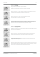


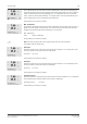


Table Of Contents
- Operation Manual Multiparameter Transmitter M400
- Content
- 1 Introduction
- 2 Safety instructions
- 3 Unit overview
- 4 Installation instruction
- 4.1 Unpacking and inspection of equipment
- 4.2 Connection of power supply
- 4.3 Connector PIN definition
- 4.3.1 TB1 and TB2
- 4.3.2 TB3 – Analog resistive 2-e conductivity sensors
- 4.3.3 TB3 – Analog resistive 4-e conductivity sensors
- 4.3.4 TB3 – Analog inductive conductivity sensors
- 4.3.5 TB3 – Analog pH / ORP sensors
- 4.3.6 TB3 – Analog ISFET sensors
- 4.3.7 TB3 – Analog oxygen sensors
- 4.3.8 TB3 – Analog dissolved carbon dioxide sensors
- 4.3.9 TB4 – ISM (digital) sensors for pH, conductivity and oxygen
- 4.4 Connection of ISM (digital) sensors
- 4.5 Connection of analog sensors
- 4.5.1 Connection of analog sensor for pH/ORP
- 4.5.2 VP cable assignment for pH/ORP sensor
- 4.5.3 TB3 – Typical wiring for analog pH/ORP sensor
- 4.5.4 Connection of analog ISFET sensor
- 4.5.5 TB3 – Typical wiring for analog ISFET sensor
- 4.5.6 Connection of analog sensor for amperometric oxygen measurement
- 4.5.7 TB3 – Typical wiring for analog sensor for amperometric oxygen measurement
- 4.5.8 Connection of analog sensor for dissolved carbon dioxide
- 4.5.9 TB3 – Typical wiring for analog dissolved carbon dioxide sensor
- 5 Placing transmitter in, or out, of service
- 6 Quick Setup
- 7 Sensor Calibration
- 7.1 Enter Calibration Mode
- 7.2 Conductivity calibration for two- or four-electrode sensors
- 7.3 Conductivity calibration for inductive sensors
- 7.4 Calibration of amperometric oxygen sensors
- 7.5 Calibration of optical oxygen sensors
- 7.6 pH calibration
- 7.7 ISFET calibration
- 7.8 Dissolved carbon dioxide calibration
- 7.9 Sensor temperature calibration (only for analog sensors)
- 7.10 Edit sensor calibration constants (only for analog sensor)
- 7.11 Sensor verification
- 8 Configuration
- 8.1 Enter configuration mode
- 8.2 Measurement
- 8.2.1 Channel Setup
- 8.2.2 Temperature source (only for analog sensors)
- 8.2.3 Parameter related settings
- 8.2.3.1 Conductivity temperature compensation
- 8.2.3.2 pH/ORP parameters
- 8.2.3.3 ISFET parameters
- 8.2.3.4 Parameters for oxygen measurement based on amperometric sensors
- 8.2.3.5 Parameters for oxygen measurement based on optical sensors
- 8.2.3.6 Adjusting sampling rate for optical sensors
- 8.2.3.7 LED Mode
- 8.2.3.8 Dissolved carbon dioxide parameters
- 8.2.4 Set averaging
- 8.3 Analog outputs
- 8.4 Set points
- 8.5 Alarm / Clean
- 8.6 ISM set up (available for pH and oxygen ISM sensors)
- 8.7 Display
- 8.8 Hold analog outputs
- 9 System
- 10 PID setup
- 11 Service
- 12 Info
- 13 Maintenance
- 14 Troubleshooting
- 14.1 Changing the fuse
- 14.2 Cond (resistive) Error messages / Warning- and Alarm list for analog sensors
- 14.3 Cond (resistive) Error messages / Warning- and Alarm list for ISM sensors
- 14.4 Cond (inductive) Error messages / Warning- and Alarm list
- 14.5 pH Error messages / Warning- and Alarm list
- 14.6 Amperometric O2 Error messages / Warning- and Alarm list
- 14.7 Optical O2 Error messages / Warning- and Alarm list
- 14.8 ISFET Error messages / Warning- and Alarm list
- 14.9 Dissolved carbon dioxide Error messages / Warning- and Alarm list
- 14.10 Warning- and Alarm indication on the display
- 15 Accessories and Spare Parts
- 16 Specifications
- 17 Default table
- 18 Warranty
- 19 Buffer tables
- METTLER TOLEDO Market Organizations

Transmitter M400 102
© 02 / 2010 Mettler-Toledo AG, CH-8606 Greifensee, Switzerland Transmitter M400
Printed in Switzerland 52 121 378
11.2.1.3 Voltage
Voltage calibration is preformed as a two point calibration.
Navigate to the Calibrate Meter screen and select Channel A and Voltage.
Enter the value for Point 1 in, volts, connected to the input. The second display line will show
the measured voltage. Press[ENTER] to begin the calibration process.
Enter the value for Point 2, in volts, of the source connected to the input.
The second display line shows the measured voltage.
Pressing the [ENTER] key after entering Point 2 will bring up a confirmation screen. Select Yes
to save the calibration values and the successful Calibration is confirmed on the display. The
transmitter will return to the measurement mode in approximately 5 seconds.
11.2.1.4 Rg diagnostic
Rg diagnostic is performed as a two point calibration. Navigate to the Calibrate Meter screen and
select Channel A and Rg Diagnostic.
Enter the value for Point 1 of the calibration according to the resistor connected across the
pH glass electrode measuring input. Press [ENTER] to begin the calibration process.
Enter the value for Point 2 of the calibration according to the resistor connected across the
pH glass electrode measuring input.
Pressing the [ENTER] key after entering Point 2 will bring up a confirmation screen. Select Yes to
save the calibration values and the successful calibration is confirmed on the display. The trans-
mitter will return to the measurement mode in approximately 5 seconds.