
Specifications

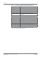
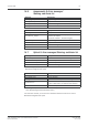
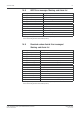

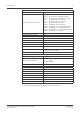

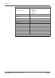
Table Of Contents
- Operation Manual Multiparameter Transmitter M400
- Content
- 1 Introduction
- 2 Safety instructions
- 3 Unit overview
- 4 Installation instruction
- 4.1 Unpacking and inspection of equipment
- 4.2 Connection of power supply
- 4.3 Connector PIN definition
- 4.3.1 TB1 and TB2
- 4.3.2 TB3 – Analog resistive 2-e conductivity sensors
- 4.3.3 TB3 – Analog resistive 4-e conductivity sensors
- 4.3.4 TB3 – Analog inductive conductivity sensors
- 4.3.5 TB3 – Analog pH / ORP sensors
- 4.3.6 TB3 – Analog ISFET sensors
- 4.3.7 TB3 – Analog oxygen sensors
- 4.3.8 TB3 – Analog dissolved carbon dioxide sensors
- 4.3.9 TB4 – ISM (digital) sensors for pH, conductivity and oxygen
- 4.4 Connection of ISM (digital) sensors
- 4.5 Connection of analog sensors
- 4.5.1 Connection of analog sensor for pH/ORP
- 4.5.2 VP cable assignment for pH/ORP sensor
- 4.5.3 TB3 – Typical wiring for analog pH/ORP sensor
- 4.5.4 Connection of analog ISFET sensor
- 4.5.5 TB3 – Typical wiring for analog ISFET sensor
- 4.5.6 Connection of analog sensor for amperometric oxygen measurement
- 4.5.7 TB3 – Typical wiring for analog sensor for amperometric oxygen measurement
- 4.5.8 Connection of analog sensor for dissolved carbon dioxide
- 4.5.9 TB3 – Typical wiring for analog dissolved carbon dioxide sensor
- 5 Placing transmitter in, or out, of service
- 6 Quick Setup
- 7 Sensor Calibration
- 7.1 Enter Calibration Mode
- 7.2 Conductivity calibration for two- or four-electrode sensors
- 7.3 Conductivity calibration for inductive sensors
- 7.4 Calibration of amperometric oxygen sensors
- 7.5 Calibration of optical oxygen sensors
- 7.6 pH calibration
- 7.7 ISFET calibration
- 7.8 Dissolved carbon dioxide calibration
- 7.9 Sensor temperature calibration (only for analog sensors)
- 7.10 Edit sensor calibration constants (only for analog sensor)
- 7.11 Sensor verification
- 8 Configuration
- 8.1 Enter configuration mode
- 8.2 Measurement
- 8.2.1 Channel Setup
- 8.2.2 Temperature source (only for analog sensors)
- 8.2.3 Parameter related settings
- 8.2.3.1 Conductivity temperature compensation
- 8.2.3.2 pH/ORP parameters
- 8.2.3.3 ISFET parameters
- 8.2.3.4 Parameters for oxygen measurement based on amperometric sensors
- 8.2.3.5 Parameters for oxygen measurement based on optical sensors
- 8.2.3.6 Adjusting sampling rate for optical sensors
- 8.2.3.7 LED Mode
- 8.2.3.8 Dissolved carbon dioxide parameters
- 8.2.4 Set averaging
- 8.3 Analog outputs
- 8.4 Set points
- 8.5 Alarm / Clean
- 8.6 ISM set up (available for pH and oxygen ISM sensors)
- 8.7 Display
- 8.8 Hold analog outputs
- 9 System
- 10 PID setup
- 11 Service
- 12 Info
- 13 Maintenance
- 14 Troubleshooting
- 14.1 Changing the fuse
- 14.2 Cond (resistive) Error messages / Warning- and Alarm list for analog sensors
- 14.3 Cond (resistive) Error messages / Warning- and Alarm list for ISM sensors
- 14.4 Cond (inductive) Error messages / Warning- and Alarm list
- 14.5 pH Error messages / Warning- and Alarm list
- 14.6 Amperometric O2 Error messages / Warning- and Alarm list
- 14.7 Optical O2 Error messages / Warning- and Alarm list
- 14.8 ISFET Error messages / Warning- and Alarm list
- 14.9 Dissolved carbon dioxide Error messages / Warning- and Alarm list
- 14.10 Warning- and Alarm indication on the display
- 15 Accessories and Spare Parts
- 16 Specifications
- 17 Default table
- 18 Warranty
- 19 Buffer tables
- METTLER TOLEDO Market Organizations

Transmitter M400 113
© 02 / 2010 Mettler-Toledo AG, CH-8606 Greifensee, Switzerland Transmitter M400
Printed in Switzerland 52 121 378
14.6 Amperometric O
2
Error messages /
W
arning- and Alarm list
Warnings Description
Warning O
2
Slope < – 90 nA Slope too big
Warning O
2
Slope > – 35 nA Slope too small
Warning O
2
ZeroPt > 0.3 nA Zero offset too big
Warning O
2
ZeroPt < – 0.3 nA Zero offset too small
Alarms Description
Watchdog time-out* SW/System fault
Error Install O
2
Jumper
In case of using InPro 6900 a jumper has to be
installed (see chapter:
Connection of Sensor – Dissolved Oxygen)
Error O
2
Slope < –110 nA Slope too big
Error O
2
Slope > – 30 nA Slope too small
Error O
2
ZeroPt > 0.6 nA Zero offset too big
Error O
2
ZeroPt < – 0.6 nA Zero offset too small
14.7 Optical O
2
Error messages / Warning- and Alarm list
Warnings Description
Chx Cal Required* ATC = 0 or measured values out of range
Chx CIP Counter Expired Limit of CIP cycles reached
Chx SIP Counter Expired Limit of SIP cycles reached
Chx Autocl. Count. Exp. Limit of autoclaving cycles reached
* If this warning is displayed, you will find more information about the cause for the warning in
Menu/Service/Diagnostics/O
2
optical
Alarms Description
Watchdog time-out* SW/System fault
Chx Change Spot** Replace OptoCap
Chx Signal error** Signal or value for temperature out of range
Chx Shaft error**
Temperature bad or stray light too high (e.g. because
a glass is ber broken) or shaft has been removed
Chx Hardware error** Electronic components fail
** According to the parameterization of the transmitter (see chapter 8.5.1 “Alarm”;
PATH: Menu/Configure/Alarm/Clean/Setup Alarm)
If an alarm has occurred, you will find more information about the cause for the alarm in
Menu/Service/Diagnostics/O
2
optical