
Specifications


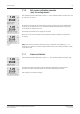


Table Of Contents
- Operation Manual Multiparameter Transmitter M400
- Content
- 1 Introduction
- 2 Safety instructions
- 3 Unit overview
- 4 Installation instruction
- 4.1 Unpacking and inspection of equipment
- 4.2 Connection of power supply
- 4.3 Connector PIN definition
- 4.3.1 TB1 and TB2
- 4.3.2 TB3 – Analog resistive 2-e conductivity sensors
- 4.3.3 TB3 – Analog resistive 4-e conductivity sensors
- 4.3.4 TB3 – Analog inductive conductivity sensors
- 4.3.5 TB3 – Analog pH / ORP sensors
- 4.3.6 TB3 – Analog ISFET sensors
- 4.3.7 TB3 – Analog oxygen sensors
- 4.3.8 TB3 – Analog dissolved carbon dioxide sensors
- 4.3.9 TB4 – ISM (digital) sensors for pH, conductivity and oxygen
- 4.4 Connection of ISM (digital) sensors
- 4.5 Connection of analog sensors
- 4.5.1 Connection of analog sensor for pH/ORP
- 4.5.2 VP cable assignment for pH/ORP sensor
- 4.5.3 TB3 – Typical wiring for analog pH/ORP sensor
- 4.5.4 Connection of analog ISFET sensor
- 4.5.5 TB3 – Typical wiring for analog ISFET sensor
- 4.5.6 Connection of analog sensor for amperometric oxygen measurement
- 4.5.7 TB3 – Typical wiring for analog sensor for amperometric oxygen measurement
- 4.5.8 Connection of analog sensor for dissolved carbon dioxide
- 4.5.9 TB3 – Typical wiring for analog dissolved carbon dioxide sensor
- 5 Placing transmitter in, or out, of service
- 6 Quick Setup
- 7 Sensor Calibration
- 7.1 Enter Calibration Mode
- 7.2 Conductivity calibration for two- or four-electrode sensors
- 7.3 Conductivity calibration for inductive sensors
- 7.4 Calibration of amperometric oxygen sensors
- 7.5 Calibration of optical oxygen sensors
- 7.6 pH calibration
- 7.7 ISFET calibration
- 7.8 Dissolved carbon dioxide calibration
- 7.9 Sensor temperature calibration (only for analog sensors)
- 7.10 Edit sensor calibration constants (only for analog sensor)
- 7.11 Sensor verification
- 8 Configuration
- 8.1 Enter configuration mode
- 8.2 Measurement
- 8.2.1 Channel Setup
- 8.2.2 Temperature source (only for analog sensors)
- 8.2.3 Parameter related settings
- 8.2.3.1 Conductivity temperature compensation
- 8.2.3.2 pH/ORP parameters
- 8.2.3.3 ISFET parameters
- 8.2.3.4 Parameters for oxygen measurement based on amperometric sensors
- 8.2.3.5 Parameters for oxygen measurement based on optical sensors
- 8.2.3.6 Adjusting sampling rate for optical sensors
- 8.2.3.7 LED Mode
- 8.2.3.8 Dissolved carbon dioxide parameters
- 8.2.4 Set averaging
- 8.3 Analog outputs
- 8.4 Set points
- 8.5 Alarm / Clean
- 8.6 ISM set up (available for pH and oxygen ISM sensors)
- 8.7 Display
- 8.8 Hold analog outputs
- 9 System
- 10 PID setup
- 11 Service
- 12 Info
- 13 Maintenance
- 14 Troubleshooting
- 14.1 Changing the fuse
- 14.2 Cond (resistive) Error messages / Warning- and Alarm list for analog sensors
- 14.3 Cond (resistive) Error messages / Warning- and Alarm list for ISM sensors
- 14.4 Cond (inductive) Error messages / Warning- and Alarm list
- 14.5 pH Error messages / Warning- and Alarm list
- 14.6 Amperometric O2 Error messages / Warning- and Alarm list
- 14.7 Optical O2 Error messages / Warning- and Alarm list
- 14.8 ISFET Error messages / Warning- and Alarm list
- 14.9 Dissolved carbon dioxide Error messages / Warning- and Alarm list
- 14.10 Warning- and Alarm indication on the display
- 15 Accessories and Spare Parts
- 16 Specifications
- 17 Default table
- 18 Warranty
- 19 Buffer tables
- METTLER TOLEDO Market Organizations
Transmitter M400 62
© 02 / 2010 Mettler-Toledo AG, CH-8606 Greifensee, Switzerland Transmitter M400
Printed in Switzerland 52 121 378
7.8.2.1 Auto Mode
Place the electrode in the first buffer solution and press the [ENTER] key to start the calibration.
The display shows the buffer the transmitter has recognized (Point 1) and the measured value.
As soon as the stabilisation criteria have been fulfilled, the display changes and prompts you to
place the electrode in the second buffer.
Place the electrode in the second buffer solution and press the [ENTER] key to go on with the
calibration.
The display shows the second buffer the transmitter has recognized (Point 2) and the measured
value.
As soon as the stabilisation criteria have been fulfilled, the display changes to show the slope
calibration factor S and the offset calibration factor Z.
After a successful calibration, the calibration values are taken over (Adjust) or were aborted
(Calibrate or Abort).
If ”Adjust” or ”Calibrate” are chosen, the message ”Calibration successful” is displayed. In any
case you will get the message ”Re-install sensor” and ”Press ENTER” on the display. After press-
ing ”ENTER” the M400 returns to the measuring mode.
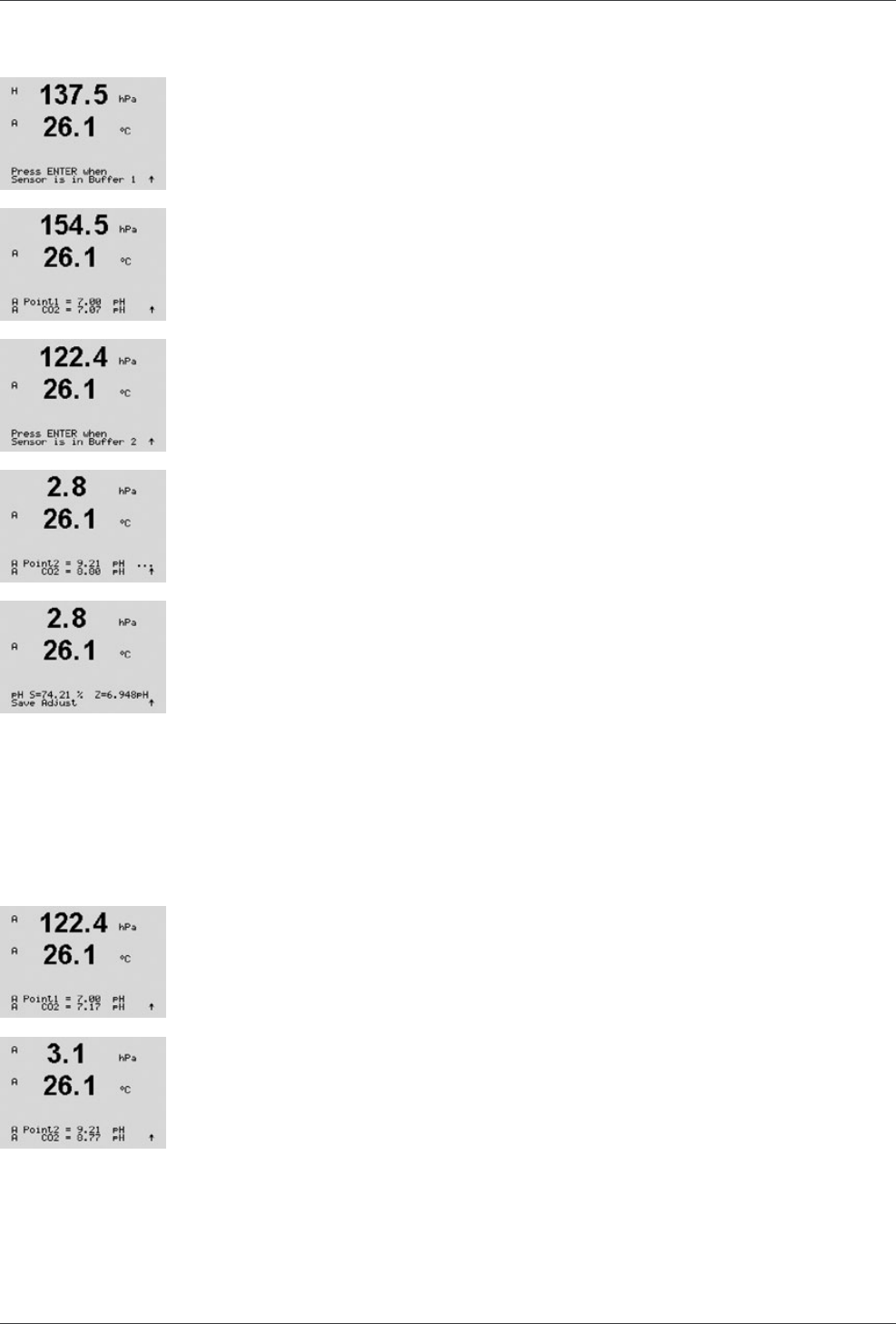
7.8.2.2 Manual Mode
Place the electrode in the first buffer solution. The display shows the buffer the transmitter has
recognized (Point 1) and the measured value. Press [ENTER] to proceed.
Place the electrode in the second buffer solution. The display shows the buffer the transmitter
has recognized (Point 2) and the measured value. Press [ENTER] to proceed.