
Specifications
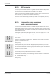
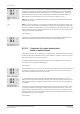


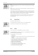
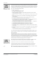
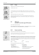
Table Of Contents
- Operation Manual Multiparameter Transmitter M400
- Content
- 1 Introduction
- 2 Safety instructions
- 3 Unit overview
- 4 Installation instruction
- 4.1 Unpacking and inspection of equipment
- 4.2 Connection of power supply
- 4.3 Connector PIN definition
- 4.3.1 TB1 and TB2
- 4.3.2 TB3 – Analog resistive 2-e conductivity sensors
- 4.3.3 TB3 – Analog resistive 4-e conductivity sensors
- 4.3.4 TB3 – Analog inductive conductivity sensors
- 4.3.5 TB3 – Analog pH / ORP sensors
- 4.3.6 TB3 – Analog ISFET sensors
- 4.3.7 TB3 – Analog oxygen sensors
- 4.3.8 TB3 – Analog dissolved carbon dioxide sensors
- 4.3.9 TB4 – ISM (digital) sensors for pH, conductivity and oxygen
- 4.4 Connection of ISM (digital) sensors
- 4.5 Connection of analog sensors
- 4.5.1 Connection of analog sensor for pH/ORP
- 4.5.2 VP cable assignment for pH/ORP sensor
- 4.5.3 TB3 – Typical wiring for analog pH/ORP sensor
- 4.5.4 Connection of analog ISFET sensor
- 4.5.5 TB3 – Typical wiring for analog ISFET sensor
- 4.5.6 Connection of analog sensor for amperometric oxygen measurement
- 4.5.7 TB3 – Typical wiring for analog sensor for amperometric oxygen measurement
- 4.5.8 Connection of analog sensor for dissolved carbon dioxide
- 4.5.9 TB3 – Typical wiring for analog dissolved carbon dioxide sensor
- 5 Placing transmitter in, or out, of service
- 6 Quick Setup
- 7 Sensor Calibration
- 7.1 Enter Calibration Mode
- 7.2 Conductivity calibration for two- or four-electrode sensors
- 7.3 Conductivity calibration for inductive sensors
- 7.4 Calibration of amperometric oxygen sensors
- 7.5 Calibration of optical oxygen sensors
- 7.6 pH calibration
- 7.7 ISFET calibration
- 7.8 Dissolved carbon dioxide calibration
- 7.9 Sensor temperature calibration (only for analog sensors)
- 7.10 Edit sensor calibration constants (only for analog sensor)
- 7.11 Sensor verification
- 8 Configuration
- 8.1 Enter configuration mode
- 8.2 Measurement
- 8.2.1 Channel Setup
- 8.2.2 Temperature source (only for analog sensors)
- 8.2.3 Parameter related settings
- 8.2.3.1 Conductivity temperature compensation
- 8.2.3.2 pH/ORP parameters
- 8.2.3.3 ISFET parameters
- 8.2.3.4 Parameters for oxygen measurement based on amperometric sensors
- 8.2.3.5 Parameters for oxygen measurement based on optical sensors
- 8.2.3.6 Adjusting sampling rate for optical sensors
- 8.2.3.7 LED Mode
- 8.2.3.8 Dissolved carbon dioxide parameters
- 8.2.4 Set averaging
- 8.3 Analog outputs
- 8.4 Set points
- 8.5 Alarm / Clean
- 8.6 ISM set up (available for pH and oxygen ISM sensors)
- 8.7 Display
- 8.8 Hold analog outputs
- 9 System
- 10 PID setup
- 11 Service
- 12 Info
- 13 Maintenance
- 14 Troubleshooting
- 14.1 Changing the fuse
- 14.2 Cond (resistive) Error messages / Warning- and Alarm list for analog sensors
- 14.3 Cond (resistive) Error messages / Warning- and Alarm list for ISM sensors
- 14.4 Cond (inductive) Error messages / Warning- and Alarm list
- 14.5 pH Error messages / Warning- and Alarm list
- 14.6 Amperometric O2 Error messages / Warning- and Alarm list
- 14.7 Optical O2 Error messages / Warning- and Alarm list
- 14.8 ISFET Error messages / Warning- and Alarm list
- 14.9 Dissolved carbon dioxide Error messages / Warning- and Alarm list
- 14.10 Warning- and Alarm indication on the display
- 15 Accessories and Spare Parts
- 16 Specifications
- 17 Default table
- 18 Warranty
- 19 Buffer tables
- METTLER TOLEDO Market Organizations
Transmitter M400 72
© 02 / 2010 Mettler-Toledo AG, CH-8606 Greifensee, Switzerland Transmitter M400
Printed in Switzerland 52 121 378
If an ISM sensor has been connected resp. configured there is furthermore the option to adjust
the polarization voltage for the sensor. Different value can be entered for the measuring mode
(Umeaspol) and for the calibration mode (Ucalpol). For entered values 0 mV to –550 mV the
connected sensor will be set to a polarization voltage of –500mV. If the entered value is less
then –550mV, the connected sensor will set to a polarization voltage of –674mV.
h
NOTE: During a process calibration, the polarization voltage Umeaspol, defined for the measur-
ing mode, will be used.
h
NOTE: If a one point calibration is executed, the transmitter sends the polarization voltage, valid
for the calibration, to the sensor. If the polarization voltage for the measuring mode and calibra-
tion mode is different, the transmitter will wait 120 seconds before starting the calibration. In this
case the transmitter will also go after the calibration for 120 seconds to the HOLD Mode, before
returning to the measuring mode again.
Press [ENTER]
The display shows the Save Changes dialog. Selecting No will discard the entered values and
return to the measurement display screen, selecting Yes will save changes made.
8.2.3.5 Parameters for oxygen measurement
based on optical sensors
If during the channel setup (see chapter 8.2.1 “Channel setup”) the parameter O2 Opt has been
chosen, the parameters calibration pressure, process pressure, ProCalPres, salinity, drift control
and relative humidity can be set resp. adjusted.
For doing these adjustments the menu “O2 optical”, that will be displayed, has to be chosen.
(see chapter 8.2.3 “Parameter related settings”)
Press [ENTER]
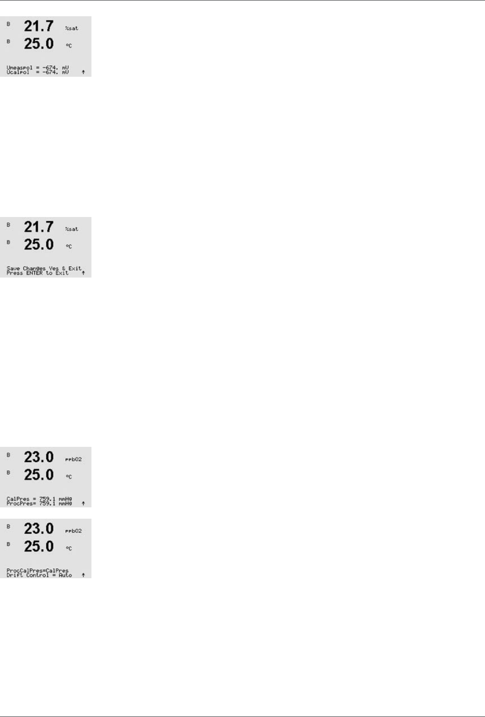
Enter the calibration pressure (line 3). The default value for CalPres is 759.8 and the default unit
is mmHg. Also the process pressure (line 4) can be modified. The units for process pressure
and calibration pressure do not have to be the same.
For the algorithm of the process calibration the applied pressure (ProcCalPres) has to be de-
fined. The value of the process pressure (ProcPres) or the calibration pressure (CalPres) can be
used. Chose the pressure, that applies during the process calibration, resp. should be used for
the algorithm.
Select the drift control for calibration as Auto (drift and time criteria have to be fulfilled) or manu-
al (The user can decide when a signal is stable enough to complete calibration). If Auto is se-
lected, the drift is checked by the sensor. If the drift criteria is not met within a defined time (de-
pending on the sensor model) the calibration times out and the message ”Calibration Not Done”
Press ENTER Enter to ”Exit” is displayed.
Press [ENTER]