Operating Instructions METTLER TOLEDO Excellence XS Analytical Balances ww w.m XS2 05 t.co Du m al R ang e www.mt.
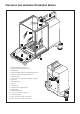
Overview of your excellence XS analytical balance 7 5 ww w.m t.
Contents Contents 1 Getting to know your balance........................................................................................................................... 9 1.1 1.2 1.3 1.4 Introduction.................................................................................................................................................................. 9 Introducing the XS analytical balances.....................................................................................................
Contents 5.5 5.6 5.7 5.8 5.9 5.10 5.11 5.12 5.13 5.14 Select dialog language............................................................................................................................................... 37 Select peripheral devices............................................................................................................................................ 37 Terminal settings...................................................................................................
Contents 7.4 7.4.1 7.4.2 7.4.3 7.4.4 Working with the “Statistics” application....................................................................................................................... 67 Statistical recording of series of weighings................................................................................................................... 67 Additive weighing to a target value..............................................................................................................
Contents 10.3.4 10.3.5 10.4 10.4.1 10.4.2 10.4.3 Additional Unit for percent weighing............................................................................................................................. 95 Special Report Information for percent weighing........................................................................................................... 95 Working with the “Percent Weighing” application..........................................................................................
Contents 17 Appendix.................................................................................................................................................... 128 17.1 17.2 Conversion table for weight units............................................................................................................................... 128 SOPs - standard operating procedures......................................................................................................................
Getting to know your balance 1 Getting to know your balance In this Section you will be given basic information about your balance. Please read right through this Section carefully even if you already have experience with METTLER TOLEDO balances; please pay special attention to the safety warnings! 1.1 Introduction Thank you for choosing a METTLER TOLEDO balance.
Getting to know your balance 10 1.4 Safety first Always operate and use your balance only in accordance with the instructions contained in this manual. The instructions for setting up your new balance must be strictly observed. If the instrument is not used according to the manufacturer's Operating Instructions, protection of the instrument may be impaired. The balance may only be used in enclosed interior rooms. It is not advised to use the balance in hazardous environments.
Setting up the balance 11 2 Setting up the balance This Section explains how to unpack your new balance, and how to set it up and prepare it for operation. When you have carried out the steps described in this Section, your balance is ready for operation. 2.1 Unpacking and checking the delivered items 2.1.1 Unpacking the balance Use the lifting strap to lift the balance out of the packaging carton.
Setting up the balance 12 The terminal is connected to the balance by a cable, so only pull the terminal just far enough out of the packing cushion to remove the protective cover. – Carefully pull the terminal out ot the bottom packing cushion and remove the protective cover. – Place the terminal on the front of the balance. – Hold the balance by the guide or handle, hold the terminal firmly with your other hand, and pull the balance and terminal together out of the bottom packing cushion.
Setting up the balance 13 2.1.
Setting up the balance 14 3 – Insert the top door of the draft shield at an angle (slightly less than 30 degrees) into the guide positioned at the back, and swivel the draft-shield door carefully down. 1 2 4 2 4 3 1 – Insert the side doors of the draft shield according to the following instructions (see Fig. 4): • Insert the side door at an angle of approx. 30° into the 2 openings (see figure for details).
Setting up the balance 15 5 2 1 – Insert the front glass of the draft shield: • In the bottom part of the balance at the front, move at an angle from the top toward the bottom until the two hooks of the front glass of the draft shield lie on the rollers. • Swivel the front glass of the draft shield up until it engages. 6 – Insert the terminal support: • First lay the cable in the guide by the terminal support. • Insert the terminal support into the opening of the front glass of the draft shield.
Setting up the balance 16 – Mount the terminal: • Place the terminal in the center of the support and push it against the balance until it swivels slightly down at the front by the terminal support. 7 Note: You can push the cable into the balance. The balance and the terminal are not fastened together by the terminal support! When transporting by hand, always hold the balance and the terminal firmly (see Section 2.7).
Setting up the balance 17 2.4 Power supply Your balance is delivered complete with an AC adapter and a country-specific power supply cable. The AC adapter is suitable for all power supply voltages in the range: 100 – 240 VAC, 50/60Hz (for exact specifications, see Section 16). Check that the local power supply voltage is in this range. If it is not, DO NOT connect the balance or the AC adapter to the power supply, and contact your METTLER TOLEDO dealer.
Setting up the balance 18 2.6 Adjusting the reading angle and positioning the terminal 2.6.1 Adjusting the reading angle For a steeper reading angle, pull both levers (A) at the side upward. You can then pull the upper part of the terminal slowly upward until it engages in the desired position. Three different setting positions are provided. If you wish to have a flatter reading angle, pull both levers (A) at the side upward, and press the lower part of the terminal downward.
Setting up the balance 19 2.7 Transporting the balance Switch off the balance and unplug the cable of the AC adapter, as well as any interface cables, from the balance. 2.7.1 Transporting over short distances If you wish to move your balance over a short distance to a new location, proceed as follows: With one hand, hold the balance by the guide for the top door of the draft shield. With your other hand, hold the terminal. Carefully lift the balance and carry it to its new location.
Setting up the balance 20 Pack the AC adapter, the power supply cable, and the individual parts (steps 7+8) – Place the AC adapter and the power supply cable in the packaging. – Place the drip tray (8) upside down in the packaging. – Place the grid weighing pan (7) upside down on the drip tray. – Push the transport protection over the weighing pan guide. – Push the guide of the top draft-shield door completely to the front.
Setting up the balance 21 – Place the set with the AC adapter in front of the set with the draft-shield glass. – Insert the terminal into the packing cushion as shown in the illustration. – Now put the top packing cushion in place, taking care to position it correctly. – Pass the lifting strap around both packing cushions (see illustration) and tighten it until it lies close against the packaging. – You can now lift the packed balance by the lifting strap and insert it into the transport carton.
Setting up the balance 22 2.8 Installing the ErgoClip To install the ErgoClip included in the delivery, or an optional ErgoClip, please proceed as follows: Before you install an ErgoClip you must switch off the balance (“On/Off” key). – Remove the grid weighing pan (SmartGrid) from the balance.. – Snap the ErgoClip onto the grid weighing pan. – Replace the grid weighing pan along with the installed ErgoClip. • The optional “flask” or “tube” ErgoClips can be inserted directly.
Setting up the balance 23 2.10 Installing the grid weighing pan cover – For the installation, remove the grid weighing pan from the weighing chamber. – Gently press the cover onto the grid weighing pan. 2.11 Below-the-balance weighing So that weighings can be carried out below the working surface (below-the-balance weighing), your balance is provided with a special hanger. 1 2 – Switch off the balance and unplug the cable of the AC adapter from the back of the balance.
Your first weighing 24 3 Your first weighing In this Section you will get to know those controls and display elements of your balance that are needed to carry out simple weighing processes. This Section provides an introduction to operating your balance. 3.1 Switching the balance on and off On Off Switch balance on: Briefly press the “On/Off” key. The balance carries out a short test as soon as it has been switched on, after which it is ready to weigh.
Basic principles for using the terminal and the software 25 4 Basic principles for using the terminal and the software This Section explains the operating and display elements of your terminal, and also explains the way the software of your balance is to be used. Please read this Section carefully, because it is the basis for all the operating steps that are explained in later Sections. 4.
Basic principles for using the terminal and the software 26 4.2 The display The illuminated, graphic display of your terminal is a “Touch Screen”. It is not only possible to read data and settings, but also to make settings and to execute functions by touching the display area. The factory setting of the balance displays the weighing result at a size so that it can easily be read. In this display mode neither the information fields nor the graphical “SmartTrac” filling guide are visible.
Basic principles for using the terminal and the software 27 5 Additional information (information fields) related to the active application, and which will make your work easier, are displayed in this area. 6 5 6 The “SmartTrac” is displayed in this area. This is a graphical filling guide, showing you at a glance the weighing range that has already been filled and the range that is still available.
Basic principles for using the terminal and the software 28 System settings I The system settings are not application-dependent, and apply to the entire weighing system (e.g. setting the dialog language). To call up the system settings, press the “I” key and then the “System” button. You will find information on the individual possible settings in Section 5.
Basic principles for using the terminal and the software 29 4.4 The typical operating sequence The typical operating sequence is described briefly below, without going into detail about special application-specific features. On Off Switch on the balance: Switch the balance on by briefly pressing the “On/Off” key. Immediately after being switched on, the balance runs the most recently used application.
Basic principles for using the terminal and the software 30 4.5 The security system in your balance Your balance’s system settings, or parts of them, can be protected against unauthorized modifications by means of a password (detailed information can be found in Section 5.9). A password is defined when the balance is shipped from the factory (see Section 5.9). However, the menu settings are chosen so that you have unrestricted access to all system settings.
System settings 31 5 System settings You will learn in this Section how to adapt the weighing system to suit your requirements. The system settings apply to the entire weighing system, and therefore to all the applications. Note: You can learn about the application-dependent settings in the description of each application. 5.1 Calling up the system settings I 5.2 Open the application menu with the “I” key, and then press the “System” button.
System settings 32 5.3 Settings for calibration and tests In these menus you can make all the settings associated with the adjustment (calibration) of your balance. In the following subsections you will find information on all the possible settings for adjustment, testing procedures and their recording. 5.3.1 Fully automatic adjustment function “FACT” You can make the settings for fully automatic adjustment using the internal adjustment weight in this menu (FACT).
System settings 33 5.3.2 Define external adjustment weight If you work with an external adjustment weight, you can specify its properties here. Note: In accordance with country-specific regulations, this function may not be available on certified balances. The following settings are available: “Weight” You can specify the weight of the external adjustment weight here. An input window appears, similar to a pocket calculator and operated in the same way.
System settings 34 5.3.3 Define external test weight If you use an external weight to check the calibration, you can enter its properties (weight, ID and certificate number) here. The same settings and input window as are used to define an external adjustment weight, described in the previous section, are available. Factory setting: 5.3.
System settings 35 Sample printout of a test using an external adjustment weight (with all print-out options selected) —— External test ——02.09.2003 15:15:27 METTLER TOLEDO Balance Type XS205DU WeighBridge SNR: 1234567890 Terminal SNR: 1234567890 SW WeighBridge 0.50 SW Terminal 0.33 Weight ID ITW-820/200 Certificate No. MT-412 Temperature 22.6 Nominal Weight 200.00000 Actual 199.99930 Diff -0.
System settings 36 5.4.1 Adaptation to the type of balance By setting the Weighing Mode you adapt the balance to the weighing type. Select the “Universal” weighing mode for all ordinary weighing processes, or “Dosing” to dispense liquid or powder materials. With this setting the balance reacts very quickly to very small changes in weight.The“Sensor Mode” setting supplies a weighing signal which is filtered to an extent which depends on the setting for the environmental conditions.
System settings 37 5.5 Select dialog language In this menu you select the language in which you wish to communicate with the balance. Factory setting: 5.6 Depends on the language package installed. Usually the language is preset to that of the country for which the balance is intended. Select peripheral devices A number of different peripheral devices can the connected to the interface(s) of your balance.
System settings 38 If you have activated a device you can adjust the interface parameters for communication with that device with the “Define” button (baud rate, bit/parity, stop bits, Handshake, end of line, character set, and continuous mode). Factory setting: “Host” (9600 baud, 8 data bits/no parity, 1 stop bit, Xon/Xoff protocol, End of line character , ANSI/WINDOWS character set, Continuous mode Off) Important: To ensure that special characters (e.g.
System settings 39 5.7 Terminal settings In this menu you can adapt the terminal to suit your needs and can adjust the display. The following parameters are available: “Brightness” Here you can adjust the brightness of the display. Use the arrow keys to adjust the brightness between 20% and 100% (in steps of 20%) as required. The brightness is modified immediately each time either of the arrow keys is pressed, so that you can see the change straightaway.
System settings 40 5.8 Date and time In this menu you can enter the date and time, and can select their display format. You can also specify whether the date or the time are to appear on the display. The following options can be set: “Date Format” (for the display) The following date formats are available: “D.MMM.YYYY” Display example: 29 May 2000 “MMM D YYYY” Display example: May 29 2000 “DD.MM.YYYY” Display example: 29.05.2000 “MM/DD/YYYY” Display example: 05/29/2000 Factory setting: “D.MMM.
System settings 41 “Date/Time Display” You can specify whether the date or the time is to be shown in the upper right-hand corner of the display: “Date” “Time” Factory setting: 5.9 The date is shown on the display The time is shown on the display “Date” Define access rights and specify the password In this menu you can define and specify a password that can be used to protect menu areas.
System settings 42 WARNING: If you forget the password, there is no way of recreating access to the protected menu area! If you have protected either the system settings as a whole or just the access rights with a password, then it is no longer possible to define another password or to remove the password protection! We therefore recommend that you write the password down and store it in a safe place! If you are unable to find the password, please contact the METTLER TOLEDO customer service department. 5.
System settings 43 5.12 Loading the factory settings In this menu you can return all the settings in the balance to the factory settings. Please note:This reset will affect all the system settings as well as all the applicationspecific settings! For security reasons you will be prompted to confirm whether you really want to load the factory settings. Select “OK” to load the factory settings, or “C” to retain the settings that have been made now.
System settings 44 “Balance Information” After pressing the “Display” button a window opens containing information about the balance and the built-in options. This information is of particular significance for service technicians. If you callring the METTLER TOLEDO customer service department you should have this information at hand.
The “Weighing” application 45 6 The “Weighing” application In this Section we describe the “Weighing” application. You will find information here about practical aspects of working with this application and about its specific settings. (Information about the system settings that are not specific to the application are to be found in Section 5.) 6.1 Select the application I 6.2 Unless the “weighing” application is already active, press the “I” key. Press the “weighing” icon in the selection window.
The “Weighing” application 46 The following settings are available on the third menu page: “Protocol”: Select the information that is to appear on the weighing printout (Section 6.2.7). “Print Key”: Specifies the behavior of the“F”key for manually printing weighing results (Section 6.2.8). “Transfer Key”: Formats the data that are output with the “Transfer” function key (Section 6.2.9).
The “Weighing” application 47 6.2.2 Select function keys Function keys offer you direct access to specific functions and settings for the application.The function keys are shown in the application on the lower edge of the display (see Section 4.2). The corresponding function is initiated by pressing one of the buttons. In this menu you can specify which functions should be made available in the application. The function keys that have a number will be displayed in the application.
The “Weighing” application 48 6.2.3 Select information fields The information fields provide continuous information about set values, measured results and so forth. The information fields are displayed in the application underneath the weighing result. Note: The information fields are only shown in the display mode in which the weight itself is represented on a small scale. In the other two display modes, the larger display of the weight uses the space taken by the information fields (Section 4.2).
The “Weighing” application 49 6.2.5 Select weighing units You can specify the weighing units with which you want to work in the “Display Unit” and “Info Unit” menus. If two different units are chosen, you can have the weighing result displayed in two different weighing units at the same time. The same range of units can be selected for the “Display Unit” as for the “Information Unit” (see also the conversion table in Chapter 17.1).
The “Weighing” application 50 6.2.7 Define printout In this menu you can specify the information that is to appear on the weighing printout. For the sake of clarity, this large menu is divided into three submenus in which you can specify the options for the printout header, the printing of the individual values, and for the footer. Options for the printout header In this submenu you can specify the information that is to be printed at the top of the weighing printout (before the results themselves).
The “Weighing” application 51 Options for printing out the individual values In this submenu you can specify the information that is to be printed for every individual weighing result (after pressing the «F» key). The following information is available for inclusion on the printouts of weights: T N G N 54.37 868.24 922.61 0.86824 g g g kg “Header”: The information specified for the header is printed (see previous paragraph). “Blank Line”: An empty line is inserted.
The “Weighing” application 52 6.2.8 “Signature”: Inserts a dotted line where the printout can be signed. “Dash Line”: Inserts a broken separating line. “3 Blank Lines”: Prints three blank lines to complete the printout (paper advance). Factory setting: “Signature” and “3 Blank Lines” are active. Selections for manual printouts The settings in the “Print Key” menu allow you to specify the behavior of the «F» (printout) key. 6.2.
The “Weighing” application 53 If you want to change the output format, touch the button next to “Data output format”. Activate “Customise” and then touch the “Define” button. This menu contains settings for the following data fields: – Net weight symbol – Weight value – Weight unit In the output data, these fields are separated by a space character. The complete data record is terminated with the end-of-line characters that were defined for the host (Section 5.6).
The “Weighing” application 54 “No. of dec. digits”: Number of decimal places (0 – 6 digits). If the set number is less than the number of decimal places displayed on the terminal, the value will be rounded to the selected number of decimal places before it is transmitted. Factory setting: Max. number of decimal places of the balance. “Sign”: When set to “Always”, the weight value is always preceded by a plus or minus sign. If you select “Neg.
The “Weighing” application 55 6.2.10 Define identifier In this menu it is possible to activate the three identifiers that are available under the “ID” key (Section 6.2.2) and to change their names. Select the ID that you wish to activate or deactivate, or whose name you want change. Note: Deactivated IDs (“Off”) are no longer available for selection under the “ID” function key. A window then appears in which you can activate the ID and change the name.
The “Weighing” application 56 6.2.12 Specifications for processing keyboard entries If an external keyboard is connected to your balance, this menu can be used to specify how the data is to be processed. The following settings are available: “Off”: No keyboard entries are processed. This setting should be used if no keyboard is connected. “Host”: The keyboard entries are not processed in the balance, but are transmitted directly to the connected PC.
The “Weighing” application 57 6.3 Working with the “weighing” application You have already seen in Section 3 how a simple weighing process is carried out. In this Section we will show you how the various functions in the “Weighing” application can be used in practice. 6.3.1 Changing the readability of the measured weight The balance is factory adjusted so that the measured weight is displayed with the maximum readability of which the particular model is capable (according to 1d).
The “Weighing” application 58 We recommend that the corresponding information fields are also activated when working with identifiers (Section 6.2.3). The information fields have the names that you have selected for the three identifiers. The example here illustrates the balance’s display after activation of the ID function key and the ID information fields. The working example here is based on ID names as defined in the example above.
The “Weighing” application 59 6.4 Adjust the balance and check the adjustment Your balance is factory set to fully automatic adjustment, FACT. FACT adjusts and linearizes the balance automatically as soon as this is made necessary by a change in the ambient temperature. You can, however, carry out a manual adjustment and/or check using the internal weight or an external weight at any time. It is assumed in the following descriptions that the appropriate function keys for adjustment and tests (Section 6.
The “Weighing” application 60 One of the two following messages will appear when the process is complete: The adjustment has been successfully completed. Press “OK” to return to the application. If a printer is connected to the balance the adjustment will automatically be recorded on a hard copy in accordance with the specifications that you have made for printing out adjustments in the system settings (Section 5.3.4). You will find a sample printout in Section 6.4.6.
The “Weighing” application 61 At the end of the adjustment procedure, you are prompted to lift off the weight. Remove the adjustment weight from the weighing pan. The balance confirms successful completion of the adjustment. Press “OK” to return to the application. If a printer is connected to the balance the adjustment will automatically be recorded on a hard copy in accordance with the specifications that you have made for printing out adjustments in the system settings (Section 5.3.4).
The “Weighing” application 62 6.4.6 Adjustment and test print-outs (sample printouts) Printout of an internal or FACT adjustment Printout of an external adjustment - Internal adjustment -03.09.2003 11:59:42 - External adjustment -03.09.2003 12:09:56 METTLER TOLEDO METTLER TOLEDO Balance Type XS205DU WeighBridge SNR: 1234567890 Terminal SNR: 1234567890 SW WeighBridge 0.50 SW Terminal 0.33 Balance Type XS205DU WeighBridge SNR: 1234567890 Terminal SNR: 1234567890 SW WeighBridge 0.50 SW Terminal 0.
The “Statistics” application 63 7 The “Statistics” application In this Section we describe the “Statistics” application. You will find information here about practical aspects of working with this application and about its specific settings. (Information about the system settings that are not specific to the application are to be found in Section 5.) 7.
The “Statistics” application 64 Apart from a small number of exceptions, the settings available for the “Statistics” application are identical with those for the “Weighing” application (Section 6.2). The only differences in the settings are described below. These concern the following menus: “Function Keys”: Additional function keys are available for the Statistics. “Info Field”: Additional information fields are available for the Statistics.
The “Statistics” application 65 7.3.3 Special statistical information fields The following settings are available on the first two pages of the information fields menu for the display of statistical values: “n”: Number of samples weighed. “x”: Mean weight of all samples. “s” and “s.rel”: Standard deviation as an absolute or as a percentage figure. “Sum”: Summed weight of all the individual weighings. “Min” and “Max”: Smallest and largest weights found in the current series of weighings.
The “Statistics” application 66 Printing the individual values The same additional settings are available in this sub menu as are provided for the header: (“Max n”,“Nominal value”,“+Tol” and “–Tol”). Factory setting: “Net” (the net weight of the current weighing). No specific statistical information is activated. An individual value is automatically printed when the “M+” function key is pressed during a series of weighings.
The “Statistics” application 67 7.3.5 Activate additive mode In this menu, which is only available in the “Statistics” application, you can switch the additive mode on or off. In weighing series made with the additive mode active you do not have to remove the samples from the weighing pan. “Off”: Additive mode is switched off. “On”: Additive mode is switched on.
The “Statistics” application 68 Place the first sample on the balance, and press the “M+” function key to pass the weight to the statistical system.As soon as the value of the weight is stable (horizontal bars disappear in the display) the value is passed to the statistical system.The header is printed out together with the result (the single value) of the current weighing (Section 7.3.4). Remove the first sample. Note: If you have activated Additive Mode (Section 7.3.
The “Statistics” application 69 7.4.2 Additive weighing to a target value The “Statistics” application provides you with additional functions that make it easier to perform additive weighing up to a specified target value. When using the statistics, you can apply these functions both to individual weighings and to series weighings. Default settings The function keys shown here must be activated so that you can enter a target value and the associated tolerances (Section 7.3.2).
The “Statistics” application 70 7.4.3 Sample printout with statistical values ------ Statistics -----3.Sep 2003 12:55 Balance Type XS205DU WeighBridge SNR: 1234567890 Terminal SNR: 1234567890 Nominal 12.04000 g +Tol 2.50 % -Tol 2.50 % n 4 x 11.888938 g s 0.331085 g s.rel 2.78 % Min 11.39287 g Max 12.07651 g Diff 0.68364 g Sum 47.55575 g The diagram opposite shows a sample printout with statistical values.
The “Statistics” application 71 7.4.4 Formulas used for calculating statistical values Calculating the mean value and standard deviation Terminology xi := Individual measurement values of a measurement series of n measurement values i = 1...
The “Formulation” application 72 8 The “Formulation” application In this Section we describe the “Formulation” application. You will find information here about practical aspects of working with this application and about its specific settings. (Information about the system settings that are not specific to the application are to be found in Section 5.) 8.
The “Formulation” application 73 Apart from a small number of exceptions, the settings available for the “Formulation” application are identical with those for the “Weighing” application (Section 6.2). The only differences in the settings are described below. These concern the following menus: “Function Keys”: Additional function keys are available for Formulation. “Info Field”: Additional information fields are available for Formulation.
The “Formulation” application 74 8.3.3 Special information fields for Formulation The following settings are available on the first two pages of the information fields menu for Formulation: “Comp. weight”: Current net weight of a component. “Nominal”: Indicates the target value for the current component that has been entered through the function key with the same name. “Net Tot.”: Displays the total net weight of all the components that have been weighed in.
The “Formulation” application 75 Printing the individual values The following special settings are available to you in this submenu for Formulation: “....... ID”: Print the identifiers that have been entered by means of the “ID” function key (Section 8.3.5). Note: The opposite example shows the factory settings for the identifiers, i.e.“Recipe ID” (ID1),“Comp. ID” (ID2) and “Lot ID” (ID3). “Comp. Counter”: Prints the current state of the component counter (number of the current component in the series).
The “Formulation” application 76 8.3.5 Special identifiers for Formulation In this menu you specify the names for the three identifiers that are available during Formulation under the “ID” function key. The factory setting for these three identifiers have the following names: “ID1” “ID2” “ID3” “Recipe ID” “Comp. ID” “Lot ID” You can deactivate individual identifiers, or can replace their names with your own text (max. 20 characters).
The “Formulation” application 77 8.4.2 Operating sequence If you are working with a weighing container, place this on the balance and press the «H», to tare the balance. Press the “ID” function key and enter the desired names (for the formula, for the first component and, if ID3 is active, also for the current lot). If you want to weigh up to a target value, press the “Nominal” function key, and specify the target weight for the first component.
The “Formulation” application 78 After you have pressed the “Result” function key, three results are displayed:“Nominal Tot.”, “Comp. Counter” and “Net Tot.”. They will, however, only be displayed if you have selected these settings (Printing the results, Section 8.3.4). You can print the complete result by pressing the «F» key. You will find a complete sample printout in Section 8.4.3.
The “Density” application 79 9 The “Density” application In this Section we describe the “Density” application. You will find information here about practical aspects of working with this application and about its specific settings. (Information about the system settings that are not specific to the application are to be found in Section 5.) 9.1 Introduction to the “Density” application. The “Density” application allows the density of solid objects, liquids and pastes to be found.
The “Density” application 80 Some of the settings that can be made for the “Density” application are identical to those for the “Weighing” application (Section 6.2). Only differences in the settings are described below. These concern the following menus: “Method”: You can select the type of density determination in this menu. “Auxiliary liquid”: You can specify the auxiliary liquid with which you will be working in this menu.
The “Density” application 81 9.3.4 Activate or deactivate the statistics The balance can maintain its own statistics for each method of density determination with the results of the density determinations which have been transferred into the statistics (max. 651500). If the statistics are activated, then at the end of each density determination you will be asked whether you want to add the results to the statistics.
The “Density” application 82 “Vol. Sinker”: The volume of the sinker can be entered with this function key (in cm3, max. 5 decimal figures). You only need activate this key if you want to use a sinker to determine the density of liquids. “Vol. Gamma”: The volume of the gamma sphere can be entered with this function key (in cm3, max. 5 decimal figures).You only need activate this key if you want to use a gamma sphere to determine the density of pastes.
The “Density” application 83 9.3.8 Special print information for density determination Additional settings for density determination, described below, are available in the three submenus in which you can specify the options for the printout header, for printing the individual values, and for the statistical printout. Note: The remaining available printout information corresponds to that for the “Weighing” application (Section 6.2.7), and is not described here.
The “Density” application 84 “Wgt in Air”: Prints the density of the sample in air (when determining the density of solid bodies). “Wgt in Liquid”: Prints the weight of the sample in the auxiliary liquid (when determining the density of solid bodies) or the weight of the sample material displaced by the sinker or by the gamma sphere. “Vol. Sample”: Prints the volume of the sample. “Density”: Prints the result of the current density determination.
The “Density” application 85 9.4 Working with the “Density” application In this Section you will learn how to work with the “Density” application and the various methods of determining density. It is assumed that the “Density” application has already been selected. The following explanations assume that the statistical function is not active (notes on using the statistical functions may be found in Section 9.5). 9.4.
The “Density” application 86 The result of the weighing is stored, after which you are prompted to immerse the solid body in the auxiliary liquid. If you are working with the hanger, place the container with the auxiliary liquid underneath the suspension equipment. If you are working with the optional density kit, follow the instructions that are included with it.
The “Density” application 87 After taring the sinker you are prompted to put the liquid whose density is to be determined into a container. If you are working with the hanger (for weighing underneath the balance), place the container with the liquid underneath the suspension equipment. If you are working with the optional density kit, follow the instructions that are included with it.
The “Density” application 88 When the sample has been tared, you will be prompted to submerge the gamma sphere in the sample substance. The weight of the substance displaced by the gamma sphere is displayed in the lower left-hand corner of the window. Press the “OK” key to accept the weight measurement.
The “Density” application 89 9.5 Using the density statistics Statistics can be collected for each method of density determination. These store all the results that you have found whilst carrying out the density determinations. Default settings In order to be able to use the statistics system, the statistic function (Section 9.3.4) and both the “Result” and “CL Result” keys must be activated (Section 9.3.6).
The “Density” application 90 -------- Density ------4.Sep 2003 12:56 Balance Type XS205DU Method Solid Liquid Water With Compensation n x 2.4358 s 0.1974 s.rel 8.11 Min 2.251 Max 2.686 Diff 0.435 Press the “F” key to print the statistics. The variables that you have activated in the “Statistics” submenu of the printout settings will be printed (Section 9.3.8). A sample printout is illustrated here. 4 g/cm3 g/cm3 % g/cm3 g/cm3 g/cm3 Without Compensation n 4 x 2.4375 g/cm3 s 0.1977 g/cm3 s.rel 8.
The “Density” application 91 9.6 Formulae used to calculate density The “Density” application is based on the formulae listed below. 9.6.
The “Density” application 92 9.7 Density table for distilled water T/°C 0.0 0.1 0.2 0.3 0.4 0.5 0.6 0.7 0.8 0.9 10. 0.99973 0.99972 0.99971 0.99970 0.99969 0.99968 0.99967 0.99966 0.99965 0.99964 11. 0.99963 0.99962 0.99961 0.99960 0.99959 0.99958 0.99957 0.99956 0.99955 0.99954 12. 0.99953 0.99951 0.99950 0.99949 0.99948 0.99947 0.99946 0.99944 0.99943 0.99942 13. 0.99941 0.99939 0.99938 0.99937 0.99935 0.99934 0.99933 0.99931 0.99930 0.99929 14.
The “Percent Weighing” application 93 10 The “Percent Weighing” application In this chapter you will be introduced to the “Percent Weighing” application. You will find practical information about working with this application and about the different settings. (You will find information about non-application-specific system settings in Chapter 5). 10.
The “Percent Weighing” application 94 With only a few exceptions, the settings available in the “Percent Weighing” application are identical to those of the “Weighing” application (Chapter 6.2). Only the settings that are different are described below. These settings are contained in the following menus: “Function Keys”: Additional function keys are available for percent weighing. “Info Fields”: Additional information fields are available for percent weighing.
The “Percent Weighing” application 95 10.3.4 Additional Unit for percent weighing In the menus for the “Display Unit” and the “Info Unit”, in addition to the known weighing units, the unit “%” (percent) is available (provided that a reference has already been determined). Note: For percent weighing you do not need to explicitly select the “%” unit, since the display unit is always switched over to“%” automatically when the reference is determined.
The “Percent Weighing” application 96 Report Footer Line On the second and third pages of this submenu you can specify which special items of information for percent weighing should be printed out in the footer line of the weighing report after the results (individual values). The same settings are available as for the header line and the individual values (“Reference%”,“Reference”,“Target value”,“+Tol” and “–Tol”, as described above).
The “Percent Weighing” application 97 10.4.2 Percent weighing to a target value The “Percent Weighing” application provides you with additional functions to make weighing to a specified target value easier. In the description that follows, it is assumed that the reference for the percent weighing has already been determined. Requirements Before you can input a target value and the associated tolerances, the function keys shown at left must be activated (Chapter 10.3.2).
The “Piece Counting” application 98 11 The “Piece Counting” application In this chapter you will be introduced to the “Piece Counting” application. You will find practical information about working with this application and about the different settings. (You will find information about the non-application-specific system settings in Chapter 5.) 11.1 Introduction to the “Piece Counting” application The “Piece Counting” application allows you to count pieces.
The “Piece Counting” application 99 With only a few exceptions, the settings available in the “Piece Counting” application are identical to those of the “Weighing” application (Chapter 6.2). Only the settings that are different are described below. These settings are contained in the following menus: “FixPcs”: Allows you to specify a fixed reference piece count. “Function Keys”: Additional function keys are available for piece counting.
The “Piece Counting” application 100 “CL Last”: Clears the last piece count that was saved (Chapter 11.4.2). “Nominal”: Specifies the desired target piece count (Chapter 11.4.3). The target piece count is also used as the reference for the tolerances (as described below). “Abs/Diff”: Switches the weight display between the number of pieces that have already been weighed and the number of pieces still needing to be weighed to reach the target piece count (Chapter 11.4.3).
The “Piece Counting” application 101 11.3.5 Additional unit for piece counting In the menus for the “display unit” and “info unit”, the unit “PCS” (pieces) is available in addition to the usual weighing units (provided that a reference piece weight was already determined). Note: When you do piece counting, you do not have to explicitly select the unit “PCS”, because the display unit is always automatically switched to “PCS” when the reference piece weight is determined.
The “Piece Counting” application 102 Reporting the result On the second and third pages of this submenu you can speciry which additional information items for piece counting should be included in the report of the results: “Max n”: Specified maximum number of piece counts in a series. “Nom, +/–Tol”: Specified target piece count and selected tolerances. “>Tol+,
The “Piece Counting” application 103 Determining the reference Place the desired number of reference pieces on the weighing pan. The balance uses these reference pieces to determine the average (mean) piece weight, which serves as the basis for piece counting. When you have placed on the weighing pan exactly the number of pieces which was programmed for the “FixPcs” function key (Chapter 11.3.2), press this function key. (The programmed reference piece count is displayed below the key, e.g.“Fix10”).
The “Piece Counting” application 104 11.4.2 Totaling piece counts and including them in statistics Settings So you can total piece counts and include them in statistics, you must activate at least one of the 3 functions keys shown at left (Chapter 11.3.3), and at least one of the function keys for reference determination (Chapter 11.4.1). In addition, we recommend you also to activate the two function keys shown at left.
The “Piece Counting” application 105 – If you saved an incorrect piece counting result by mistake, you can remove it from the statistics with the “CL Last” function key. However, this is only possible for the last result that was saved. The “CL Last” function key is only active if there are values saved in memory; otherwise the key is dimmed and cannot be operated. After you have cleared a result, the key is inactivated and only functions again after you have included the next result in the statistics.
The “Piece Counting” application 106 11.4.3 Counting to a target value The “Piece Counting” application has additional functions which make it easier for you to count to a specified target value. You can use these functions for individual piece counts as well as for series of piece counts with statistics. In the following description it is assumed that the reference for the piece count has already been determined.
The “Piece Counting” application 107 11.4.4 Example of a piece counting report with statistical values ---- Piececounting ----1.Sep 2004 17:34 Balance Type XS204 WeighBridge SNR: 1234567890 Terminal SNR: 1234567890 Nominal 110.00 PCS +Tol 2.50 % -Tol 2.50 % RefPcs 10 PCS PcsWgt 0.9088 g NetPcs 110 PCS 1 110 PCS RefPcs 10 PCS PcsWgt 0.9088 g NetPcs 105 PCS 2T+ 0
The “LabX Client” application 108 12 The “LabX Client” application This section provides an introduction to the “LabX Client” application. It provides information on starting the application and the setting options (for information on non-application-specific system settings, see section 5). 12.1 Introduction to the “LabX Client” application The “LabX Client” application registers your balance as a client in the “LabX balance” PC application (“LabX light balance” or “LabX pro balance”).
Software updates 109 13 Software updates METTLER TOLEDO is continuously improving its software for the benefit of customers. So that you, the customer, can benefit quickly and easily from further developments, METTLER TOLEDO makes the latest software versions available on the internet. The software made available on the internet has been developed by Mettler-Toledo GmbH using processes that meet the guidelines of ISO 9001.
Software updates 110 13.4 Loading the new software into the balance Before you can load the software obtained from the internet into the balance, you must connect the balance through the RS232 cable to the serial interface of your computer. Note: The cable must always be connected to the RS232C interface that is permanently fitted at the factory! Set the interface on the balance to the following values (detailed information on these system settings can be found in Section 5.6).
Software updates 111 You can begin the updating process once you have made the necessary settings and checked that the connection is operating. Click on “Start Software Update Procedure” to do this. Follow the instructions provided by e-Loader II; these will guide you step-by-step through the updating process. e-Loader II will ask you whether you want to save the current balance settings on your computer. We recommend that you carry out this data backup.
Software updates 112 13.5 Saving and reloading balance settings As well as balance software updates, e-Loader II also offers a data backup function whereby the current balance settings can be copied to a PC. This means that you have a backup copy of your settings available at all times. If necessary, you can copy this back into the balance. The function can also be used to copy the settings from one balance to another.
Error and status messages 113 14 Error and status messages 14.1 Error messages occurring during normal operation Most error messages appear in plain text directly in the respective application, and usually accompanied by a text describing how to correct the error. Error messages of this type are self-explanatory and therefore not mentioned below. The following error messages can appear instead of the weighing result: Overload The weight on the pan exceeds the weighing capacity of the balance.
Error and status messages 114 14.3 Status messages Status messages are displayed by means of small icons (symbols) in the top right of the display (close to the date or time, see Section 4.2). The status icons indicate the following: The balance would like to carry out a fully automatic FACT adjustment but is unable because another operating sequence is running.
Cleaning and service 115 15 Cleaning and service Periodically clean the weighing pan, the drip tray, the housing, and the terminal of your balance using the brush supplied with it. To clean the weighing chamber thoroughly, swivel the glasses of the draft shield away from the balance and pull them out of their fastenings. Carefully raise the front of the weighing pan and lift it out of the guide. Pull the drip tray away from the balance.
Technical data and accessories 116 16 Technical data and accessories In this Section you will find the most important technical data for your balance. Accessories from the METTLER TOLEDO range increase the functionality of your balance and open up additional areas of application. In this chapter you will find a list of the options currently available. 16.
Technical data and accessories 117 16.1.1 Explanatory notes for the METTLER TOLEDO AC adapter METTLER TOLEDO balances are operated with a certified external power supply which conforms to the requirements for Class II double insulated equipment and it is not provided with a protective earth connection but with a functional earth connection for EMC puposes.
Technical data and accessories 118 16.2 Model-specific technical data Limit values Model XS64 XS104 XS204DR XS204 Maximum load 61 g 120 g 220 g 220 g Maximum load, fine range – – 81 g – Readability 0.1 mg 0.1 mg 1 mg 0.1 mg Readability, fine range – – 0.1 mg – Taring range 0…61 g 0…120 g 0…220 g 0…220 g Repeatability (sd) 0.1 mg (60 g)4) 0.1 mg (100 g)4) 0.7 mg (200 g)4) 0.1 mg (200 g)4) Repeatability (sd) at low load 0.07 mg (10 g) 0.07 mg (10 g) 0.5 mg (10 g) 0.
Technical data and accessories 119 Limit values Model XS105DU XS205DU Maximum load 120 g 220 g Maximum load, fine range 41 g 81 g Readability 0.1 mg 0.1 mg Readability, fine range 0.01 mg 0.01 mg Taring range 0…120 g Repeatability (sd) 0.1 mg (100 g) Repeatability (sd) at low load 0.05 mg (10 g)4) Repeatability (sd), fine range 0.035 mg (40 g) 0.04 mg (80 g)4) Repeatability (sd), fine range at low load 0.02 mg (10 g)4) 0.02 mg (10 g)4) Linearity 0.2 mg 0.
Technical data and accessories 120 16.2.1 Zero-setting range and switch-on zero range for certified balances Zero-setting range Certified balances can only be set to zero within ± 2% of the maximum capacity. Outside this range, the balance must be tared. Switch-on zero range Certified balances can only be started up if the load on the balance is within the range -5 g… +28 g relative to factory zero (balance with empty weighing pan).
Technical data and accessories 121 16.3 Dimensions of the XS analytical balances 322 296 300 150 56 59 122 200.5 147.
Technical data and accessories 122 16.4 Specifications of the RS232C interface Interface type: Voltage interface according to EIA RS-232C/DIN 66020 (CCITT V24/V.28) Max. cable length: 15m Signal level: Outputs: Inputs: +5V ... +15V (RL = 3 – 7kΩ) +3V ... 25V –5V ... –15V (RL = 3 – 7kΩ) –3V ...
Technical data and accessories 123 16.6 MT-SICS Interface commands and functions Many of the balances and scales used have to be capable of integration in a complex computer or data acquisition system. To enable you to integrate balances in your system in a simple manner and utilize their capabilities to the full, most balance functions are also available as appropriate commands via the data interface.
Technical data and accessories 124 The MT-SICS commands listed below is a selected list of available commands. For additional commands and further information please refer to the Reference Manual “MT-SICS for Excellence series 11780711” downloadable from the Internet under www.mt.com/xs-analytical. S – Send stable weight value Command S Send the current stable net weight value. SI – Send value immediately Command SI Send the current net weight value, irrespective of balance stability.
Technical data and accessories 125 16.7 Accessories You can increase the functionality of your balance with accessories from the METTLER TOLEDO range. The following options are available: Drucker RS-P42: Printer with connection cable RS232, for recording results 00229265 BT-P42: Bluetooth printer with wireless connection to the balance 11132540 Optional interfaces RS232C (second RS232C interface) 11132500 LocalCAN: Connecting for max.
Technical data and accessories 126 Input/output devices ErgoSens: programmable sensor for hands-off operation, cable length = 0.
Technical data and accessories 127 Various Metal door with cutout for use on XS balance when operating with a LV11 automatic feeder 11106715 Wall fixture for terminal 11132665 Stand for terminal and printer for XP/XS 11106730 Terminal extension cable, length = 4.
Appendix 128 17 Appendix 17.1 Conversion table for weight units Kilogram 1 kg = 1000.0 g 1g = Milligram 1 mg = 0.001 g 1g = 1000.0 mg Microgram 1 µg = 0.000001 g 1g = 1000000.0 µg Carat 1 ct = 0.2 g 1g = 5.0 ct Pound 1 lb = g 1g ≈ 0.00220462262184878 lb Ounce (avdp) 1 oz = 28.349523125 g 1g ≈ 0.0352739619495804 oz Ounce (troy) 1 ozt = 31.1034768 g 1g ≈ 0.0321507465686280 ozt Grain 1 GN = 0.06479891 g 1g ≈ Pennyweight 1 dwt = 1.
Appendix 129 17.2 SOPs - standard operating procedures In the documentation of a GLP test, the SOPs are a small, but very important part. Practical experience confirms that SOPs written in-house are followed much better than SOPs written by an an external, anonymous source. You will find below a brief overview of the responsibilities in relation to SOPs, as well as a checklist for creating an SOP.
Appendix 130 Contents of the SOP 1. Introduction and objective 2. Material required 3. Description of work steps 4. Description of documentation 5. Data processing and evaluation 6. Documents, samples, etc., to be preserved 7.
Index 131 18 Index A AC adapter 10, 17, 117 Accessories 10, 125 Access rights 41 Additive mode 67 Adjusting the reading angle 18 Adjustment 32 Adjustment (calibration) 59 Adjustment with an external weight 60 Adjustment with the internal weight 59 Ambient conditions 36 Application-specific settings 27 Applications 27 Assembling the balance 13 Automatic zero setting 36 AutoZero 36 Auxiliary liquid 80, 85 B Backup copy 112 Balance information 43 Balance parameters 35
Index 132 P Pack 19 Password 30, 41 Paste 87 Percent Weighing application 93 Peripheral devices 10, 37 Piece counting 98 Positioning the terminal 18 Position of the handles 17 Power supply 17, 116 Power supply voltage 10 Power supply voltages 17 Printout 52 Protection and standards 116 Protection of the instrument 10 R Reference 94 Reference piece count 99 Reference weight 96 Relative standard deviation 71 Reload function 112 Remove terminal 18 Repeatability 36 Re
To protect your METTLER TOLEDO product’s future: METTLER TOLEDO Service assures the quality, measuring accuracy and preservation of value of all METTLER TOLEDO products for years to come. Please send for full details about our attractive terms of service. Thank you. *P11780564* Subject to technical changes and to changes in the accessories supplied with the instruments. © Mettler-Toledo AG 2006 11780564D Printed in Switzerland 0612/2.