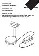
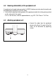
Installation and Maintenance Instructions Installations- und Wartungsanleitung METTLER TOLEDO PS7-X Paint Mixing Scales with PS-EX1 Power Supply Unit Farbmischwaagen PS7-X mit Speisegerät PS-EX1 METTL ER TO LEDO + Yes Un Men it u – No Ne Comxt p Last Com p max. 710 0g PS7 Facto r Mod Ente e r O/ On/OT ff d= 0.
Contents / Inhaltsverzeichnis English 1 2 3 4 4.1 4.2 4.3 5 5.1 5.2 6 6.1 6.2 6.3 7 8 9 Deutsch 1 2 3 4 4.1 4.2 4.3 5 5.1 5.2 6 6.1 6.2 6.3 7 8 I II III Documentation for the PS7-X Paint Mixing Scale with PS-EX1 Power Supply Unit ............................................................. 5 Application range .......................................................................... 5 Cautionary notes regarding installation ............................................ 6 Installation on the scale ......
1 Documentation for the PS7-X Paint Mixing Scale with PS-EX1 Power Supply Unit The PS7-X Paint Mixing Scale with the PS-EX1 Power Supply Unit is accompanied by the following documentation: • Installation and maintenance instructions • Operating instructions These installation and maintenance instructions apply to all scales with a type designation containing the letters PS7-X.
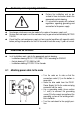
3 Cautionary notes regarding installation ▲ ▲ ▲ ▲ ▲ 4 ▲ Perform the installation only as described in these instructions and in the appropriate control drawing. It is essential to comply with national regulations regarding grounding and connection to the power supply. No changes whatsoever may be made to the scale or the power supply unit. Service work and repairs must be carried out only by personnel authorized by METTLER TOLEDO.
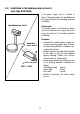
4.2 Ensuring admissibility of the peripheral unit If a peripheral unit needs to be connected, its RS232 interface must also be intrinsically safe and approved to maintain the intrinsic safety. • Ensure that the electrical limiting values of the peripheral match the limiting values printed on the scale next to the socket. If this is not the case, install an approved barrier, e.g. MTL 7061 Pac or 7161 Pac. 4.
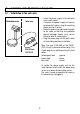
5 Installation of the PS-EX1 Power Supply Unit 5.1 Installation in the safe area Hazardous area • Install the power supply in the safe area near a wall socket. If required, the power supply unit can be permanently fixed by using the mounting plates and the 4 screws. • Route the power line cable and the cable to the scale so that they are protected against damage. Cables must not be kinked or bent at sharp angles. • Plug the power plug into the wall socket of the building electrical installation.
5.2 Installation in the hazardous area of zone 2 (only type 21201489) If the power supply unit is installed in zone 2, the power cable must be attached to the screw terminals of the building electrical installation. Hazardous area, zone 1 METTL ER TOL Requirement An all-pole power disconnecting device must be installed on the supply side of the screw terminals of the building electrical installation. EDO + Yes Unit Men u – No Nex Com t p Last Com p max.
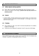
6 Operation and maintenance 6.1 Safety measures during operation ▲ ▲ Power supply unit and scale may be operated only when the housing is closed. Because of the danger of static charge, a protective cover may only be used if it is statically uncritical. 6.2 Control • Inspect the cables, connectors and accessories at regular intervals. Ensure they are free from cracks and other mechanical or chemical damage. If such damage is found, inform METTLER TOLEDO service. 6.
8 Technical data PS-EX1 Power Supply Unit Classification 230 V type Mains input Safety output Classification 120 V type Mains input Safety output Dimensions (w x d x h) Hole distance Weight Degree of enclosure protection Ambient temperature ATEX (EEx II 2 G); [EEx ib] II B; EX nA II T4 (Zone 2) 230 V, 50 Hz, 60 mA; Um= 250 V Uo: 14.3 V, Io: 2.28 A, Po: 4.2 W, Co: 2.28 µF, Lo/Ro: 0.25 mH/Ω Associated Int. Safe, output Class I, Div 1 / GP C,D 120 V, 60 Hz, 120 mA; Um= 250 V Uo: 14.3 V, Io: 2.28 A, Po: 4.
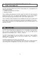
9 FCC and Canadian EMC reglementation This equipment has been tested and found to comply with the limits for a Class A digital device, pursuant to both Part 15 of the FCC Rules and the radio interference regulations of the Canadian Department of Communications. These limits are designed to provide reasonable protection against harmful interference when the equipment is operated in a commercial environment.
1 Unterlagen zur Farbmischwaage PS7-X mit Speisegerät PS-EX1 Zur Farbmischwaage PS7-X mit Speisegerät PS-EX1 erhalten Sie folgende Unterlagen: • Installations- und Wartungsanleitung • Bedienungsanleitung Die vorliegende Installations- und Wartungsanleitung gilt für alle Waagen, deren Typbezeichnung die Buchstaben PS7-X enthält. Die einzelnen Modellbezeichnungen können zusätzlich noch Zahlen zur Angabe des Wägebereichs sowie weitere Buchstaben zur Kennzeichnung von Spezialausführungen enthalten.
3 Sicherheitshinweise zur Installation ▲ ▲ ▲ ▲ ▲ 4 ▲ Installation nur nach dieser Anleitung und gemäss dem entsprechenden Anschlussplan. Nationale Vorschriften zur Erdung und zum Anschluss ans Netz unbedingt einhalten. Jegliche Veränderungen an Waage und Speisegerät sind untersagt. Servicearbeiten und Reparaturen dürfen nur von Personal durchgeführt werden, das von METTLER TOLEDO autorisiert ist.
4.2 Zulässigkeit des Peripheriegeräts sicherstellen Wenn ein Peripheriegerät angeschlossen werden soll, muss dessen RS232-Schnittstelle zum Erhalt der Eigensicherheit ebenfalls eigensicher und zugelassen sein. • Prüfen Sie, ob die elektrischen Grenzwerte des Peripheriegeräts mit den Grenzwerten übereinstimmen, die neben der Buchse an der Waage aufgedruckt sind. Falls dies nicht der Fall ist, eine zugelassene Barriere installieren, z.B. MTL 7061 Pac oder 7161 Pac. 4.
5 Installation des Speisegeräts PS-EX1 5.1 Installation im sicheren Bereich • Speisegerät im sicheren Bereich nahe einer Steckdose installieren. Falls erforderlich, kann das Speisegerät mit den Montageplatten und 4 Schrauben fest installiert werden. • Netzkabel und Kabel zur Waage so verlegen, dass sie vor Beschädigung geschützt sind. Kabel nicht knicken oder stark biegen. • Netzstecker in die Netzsteckdose der Hausinstallation stecken.
5.2 Installation in explosionsgefährdeter Umgebung der Zone 2 (nur für Typ 21201489) Wird das Speisegerät in Zone 2 installiert, muss das Netzkabel mit Schraubklemmen an die Hausinstallation angeschlossen werden. Ex-Zone 1 oder 2 METTL ER TOL Voraussetzung Eine allpolige Netz-Trennvorrichtung muss den Schraubklemmen der Hausinstallation vorgeschaltet sein. EDO + Yes Unit Men u – No Nex Com t p Last Com p max. 7100g Fact or Mod Ente e r O/T On/O ff d= 0.
6 Betrieb und Wartung 6.1 Sicherheitsmassnahmen im Betrieb ▲ ▲ Speisegerät und Waage dürfen nur bei geschlossenem Gehäuse betrieben werden. Die Verwendung einer Schutzhülle ist wegen der Gefahr von elektrostatischer Aufladung nur zulässig, wenn sie elektrostatisch unbedenklich ist. 6.2 Kontrolle • Kabel, Stecker und Zubehörteile in regelmässigen Intervallen überprüfen. Sicherstellen, dass sie keine Risse oder andere mechanische oder chemische Beschädigungen aufweisen.
8 Technische Daten Speisegerät PS-EX1 Klassifizierung 230 V Typ ATEX (EEx II 2 G); [EEx ib] II B; EX nA II T4 (Zone 2) Netzanschluss 230 V, 50 Hz, 60 mA; Um= 250 V Daten eigensicherer Ausgang Uo: 14,3 V, Io: 2,28 A, Po: 4,2 W, Co: 2,28 µF, Lo/Ro: 0,25 mH/Ω Klassifizierung 120 V Typ Associated Int.
I Anschlussplan/Installation Drawing CENELEC 21201489 / 230 V Explosionsgefährdeter Bereich / Hazardous Area Zone 1, IIB, T4 Zugelassene Geräte mit eigensicherer Daten-Schnittstelle Approved Equipment with intrinsically safe data I/O Sicherer Bereich / Safe Area entweder/oder either/or TXD [3] GND [3] RS232 Data I/O max. 10 m Peripheral equipment with approved Data I/O or with approved barrier.
II US Control Drawing 21201484A Hazardous Area Safe Area CL I, DIV 1, GP C,D FM Entity approved equipment with intrinsically safe data I/O [3] Scale PS7(a)-(b)X [1] Data I/O Data I/O Pin 2 to 5 Pin 3 to 5 Voc: 11 V Vmax: 11 V Isc: 26 mA Imax: 26 mA Ci: 0 Ca: 1 µF La: 15mH Li: 0 TXD either / or connection GND RS232 data I/O max. length 10 m [1] Temperature limits: 0 to 40 °C For an individual scale, numbers and letters may replace the letters “a” and “b” in brackets.
III Installation Drawing for Canada 21202517A Dessin d’installation pour le Canada Hazardous Area Emplacement dangereux CL I, DIV 1, GP C,D Safe Area Zone saine TXD Control room equipment grounding screw poste de mise [2] à terre. 8m [3] RXD 10 m Data I/O Appareil en zone saine GND RS232 data I/O Scale / Balance PS7(a)-(b)X [1] power supply cable (blue) câble d'alimentation (bleu) CSA Certified Zener barriers rated each 9V max. and 350Ω min. Barrières Zener certifiées CSA, specifiée 9V max.
To protect your METTLER TOLEDO product’s future: METTLER TOLEDO service assures the quality, measuring accuracy and preservation of value of all METTLER TOLEDO products for years to come. Please send for full details about our attractive terms of service. Thank you. Subject to technical changes and to the availability of the accessories supplied with the instruments.