OPERATING INSTRUCTIONS Acheron® Screen Channel Loudspeakers Acheron 100, Acheron 80, and Acheron LF Keep these important operating instructions. Check www.meyersound.com for updates.
DECLARATION OF CONFORMITY ACCORDING TO ISO/IEC GUIDE 22 AND EN 45014 Manufacturer’s Name: Meyer Sound Laboratories Inc.
SYMBOLS USED These symbols indicate important safety or operating features in this booklet and on the chassis: ! Dangerous voltages: risk of electric shock Important operating instructions Frame or chassis Protective earth ground Pour indiquer les risques résultant de tensions dangereuses Pour indequer important instructions Masse, châssis Terre de protection Warnung vor gefährlicher elektrischer Spannung Wichtige Betriebsanweisung oder Gebrauchsanleitung Rahmen oder Gehäuse Masse Schutzleiter
SAFETY SUMMARY English To reduce the risk of electric shock, disconnect the loudspeaker from the AC mains before installing audio cable. Reconnect the power cord only after making all signal connections. Connect the loudspeaker to a two-pole, three-wire grounding mains receptacle. The receptacle must be connected to a fuse or circuit breaker. Connection to any other type of receptacle poses a shock hazard and may violate local electrical codes.
CONTENTS Chapter 1: Introduction How to Use This Manual Acheron Screen Channel Loudspeaker Chapter 2: Power Requirements AC Connector AC Power Distribution Acheron Voltage Requirements Acheron Current Requirements Powering Up the Acheron Electrical Safety Guidelines Chapter 3: Amplification and Audio Audio Connectors Limiting Amplifier Cooling System Chapter 4: Integrating Acheron LF Loudspeakers Integrating Acheron LF Loudspeakers Galileo Loudspeaker Management System Using Digital Signal Processors an
CONTENTS vi
CHAPTER 1: INTRODUCTION HOW TO USE THIS MANUAL Make sure to read these operating instructions in their entirety before configuring a system with Acheron® loudspeakers. In particular, pay close attention to material related to safety issues. As you read these operating instructions, you will encounter the following icons for notes, tips, and cautions: NOTE: A note identifies an important or useful piece of information relating to the topic under discussion.
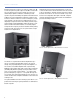
CHAPTER 1: INTRODUCTION Boasting a frequency response of 38 Hz to 17 kHz at ±4 dB, as well as a generous peak output of 139 dB at 1 meter with very low distortion, the Acheron stands up to the most demanding of digital soundtracks, maintaining a wide dynamic range and full fidelity. Designed and manufactured at Meyer Sound's headquarters in Berkeley, California, the Acheron's drivers include one 15-inch low-frequency neodymium magnet cone driver and one high-frequency 4-inch diaphragm compression driver.
ACHERON OPERATING INSTRUCTIONS Acheron LF Loudspeaker The Acheron LF loudspeaker can be paired with the Acheron 80 or Acheron 100 screen channel loudspeaker to deliver the low-frequency headroom required by larger theatres. The self-powered Acheron LF with dual 15-inch drivers boosts the headroom on the LCR channels by converting each Acheron loudspeaker to a system with three low-frequency drivers in an aligned column.
CHAPTER 1: INTRODUCTION 10
CHAPTER 2: POWER REQUIREMENTS The Acheron loudspeaker combines advanced loudspeaker technology with equally advanced power capabilities. Understanding power distribution, voltage and current requirements, and electrical safety guidelines is critical to the safe operation of the Acheron. AC Power Cable with Edison Adapter The Acheron can be powered from a standard three-prong Edison outlet with an L6-20 to Edison adapter (available for purchase from Meyer Sound; PN 27.033.024.03).
CHAPTER 2: POWER REQUIREMENTS AC POWER DISTRIBUTION ACHERON VOLTAGE REQUIREMENTS All components in an audio system (self-powered loudspeakers, processors, etc.) must be properly connected to an AC power distribution system, to ensure that AC line polarity is preserved and that all grounding points are connected to a single node or common point using the same cable gauge as the neutral and line cables.
ACHERON OPERATING INSTRUCTIONS ■ Burst Current — The maximum rms current during a period of around one second. The Burst Current is used as a rating for magnetic breakers. It is also used for calculating the peak voltage drop in long AC cable runs according to the following formula: V pk (drop) = I pk x R (cable total) ■ Ultimate Short-Term Peak Current — A rating for fastreacting magnetic breakers. ■ Inrush Current — The spike of initial current encountered when powering on.
CHAPTER 2: POWER REQUIREMENTS ■ Make sure the AC power cable for the loudspeaker has the appropriate power plug (on the other end) for the area in which you will operate the loudspeaker. ■ Do not operate the unit if the power cable is frayed or broken. ■ Keep all liquids away from the Acheron to avoid hazards from electrical shock.
CHAPTER 3: AMPLIFICATION AND AUDIO The Acheron drivers are powered by a two-channel proprietary Meyer Sound amplifier with MOSFET output stages. The audio signal is processed with an electronic crossover, correction filters for phase and frequency response, and driver protection circuitry. Each channel has peak and rms limiters that prevent driver over-excursion and regulate the temperature of the voice coil.
CHAPTER 3: AMPLIFICATION AND AUDIO NOTE: Most source devices are capable of driving loads no smaller than 10 times their output impedance. CAUTION: Make sure that all cabling for ! looped loudspeakers is wired correctly (Pin 1 to Pin 1, Pin 2 to Pin 2, and so forth) to prevent the polarity from being reversed. If one or more loudspeakers in a system have reversed polarity, frequency response and coverage will be significantly degraded.
ACHERON OPERATING INSTRUCTIONS AMPLIFIER COOLING SYSTEM Dust and the Amplifier Module The Acheron uses a forced-air cooling system with two fans (one variable-speed, ultra low-noise primary fan and one reserve fan) to prevent the amplifier module from overheating. The fans draw air in through ducts on the front of the cabinet, over the heat sink, and out the rear of the cabinet. Because dust does not accumulate in the amplifier circuitry, its life span is increased significantly.
CHAPTER 3: AMPLIFICATION AND AUDIO 18
CHAPTER 4: INTEGRATING ACHERON LF LOUDSPEAKERS INTEGRATING ACHERON LF LOUDSPEAKERS To meet the SPL and low frequency headroom requirements of large rooms, the Acheron 100 or Acheron 80 can be daisy-chained with the Acheron LF loudspeaker, creating a system with three low frequency drivers and one high frequency driver. Adding an Acheron LF yields approximately a 10 dB boost in the low frequency range, depending on loading conditions and room acoustics.
CHAPTER 4: INTEGRATING ACHERON LF LOUDSPEAKERS GALILEO LOUDSPEAKER MANAGEMENT SYSTEM The Galileo® loudspeaker management system was designed by Meyer Sound as a comprehensive solution for driving and aligning loudspeakers, especially those comprised of its self-powered loudspeakers.
CHAPTER 5: MOUNTING Strategically placed 3/8-inch threaded points on the side corners of the Acheron cabinet allow the unit to be secured to floors with uptilt or downtilt using the optional mounting brackets. The Acheron can also be mounted on top of the Acheron LF loudspeaker, also with uptilt or downtilt, using the optional stacking brackets. Both brackets are available for purchase from Meyer Sound.
CHAPTER 5: MOUNTING Floor Mounting Acherons and Acheron LFs To floor mount an Acheron or Acheron LF: 1. Remove the two 3/8-16 x 1.5-inch screws at the bottom of each loudspeaker side (four total). Floor Mounting Acherons with Downtilt and Uptilt The Acheron floor mount brackets can mount loudspeakers with downtilt or uptilt. Available angles are 3-18 degrees in 3-degree increments. The direction in which the brackets are oriented determines whether the loudspeaker can be mounted with downtilt or uptilt.
ACHERON OPERATING INSTRUCTIONS Floor Mount Downtilt Angles Floor Mount Uptilt Angles When the floor mount brackets are oriented with the bracket’s large end toward the rear of the loudspeaker, the Acheron can be mounted with downtilt angles of 3-18 degrees in 3-degree increments. When the floor mount brackets are oriented with the bracket’s large end toward the front of the loudspeaker, the Acheron can be mounted with uptilt angles of 3-18 degrees in 3-degree increments.
CHAPTER 5: MOUNTING ACHERON STACKING BRACKET Acheron Stacking Bracket Kit Contents One Acheron can be stacked on top of the Acheron LF and secured with the Acheron stacking brackets. The stacked Acheron can be mounted with downtilt and uptilt angles of 0–16 degrees. The Acheron stacking bracket kit (PN 40.188.025.01) includes the following parts.
ACHERON OPERATING INSTRUCTIONS 3. Remove the two 3/8-16 x 1.5-inch screws at the top of each side of the Acheron LF (four total). These screws will be used to secure the stacking bracket to the Acheron LF. 6. Secure the right bracket to the right side of the Acheron LF with the remaining two screws (previously removed) and the remaining two small flat washers. Install the bracket so its rubber gasket faces the loudspeaker. 7. Secure the stacking brackets to the Acheron with the four 3/8-16 x 1.
CHAPTER 5: MOUNTING Stacking Acherons with Downtilt and Uptilt Stack Mount Downtilt Angles The Acheron stacking brackets can mount Acherons with either downtilt or uptilt. Available angles are anywhere from 0–16 degrees. The direction in which the brackets are oriented determines whether the loudspeaker can be mounted with downtilt or uptilt.
ACHERON OPERATING INSTRUCTIONS Stack Mount Uptilt Angles When the stacking brackets are oriented with the bracket’s large end toward the front of the loudspeakers, the Acheron can be mounted with uptilt angles of up to 16 degrees. +16° +8° 0° Acheron Floor Mount Bracket Oriented for Uptilt Make sure to install the brackets so the rubber gasket faces the loudspeaker. This ensures that the loudspeaker will not get scratched when adjusting the uptilt angle.
CHAPTER 5: MOUNTING 28
CHAPTER 6: THE RMS REMOTE MONITORING SYSTEM An optional RMS remote monitoring system module can be installed in the Acheron, allowing it to be connected to an RMS network. RMS allows real-time monitoring of multiple Meyer Sound self-powered loudspeakers from a Windowsbased computer. The RMS host computer communicates with Meyer Sound loudspeakers (equipped with RMS modules) via a simple twisted pair network, or an Ethernet network using an FT-10 to Ethernet adapter.
CHAPTER 6: THE RMS REMOTE MONITORING SYSTEM The RMS software displays all loudspeakers on the network in a panel with icons, Meter views, and Text views that can be customized to suit your needs. Loudspeaker data is updated 2–5 times per second. Individual loudspeakers can be physically identified with the Wink option in RMS, which lights the Wink LED on the RMS module for that particular loudspeaker.
ACHERON OPERATING INSTRUCTIONS Reset Button Pressing the Reset button causes the RMS module’s firmware to reboot; this will not affect whether the loudspeaker is commissioned (which is stored in flash memory). You can simultaneously press the Reset and Service buttons to reset the RMS module and decommission the loudspeaker from the network (see “Resetting the RMS Module” on page 31). Activity LED (Green) The green Activity LED flashes continuously when the loudspeaker has been successfully commissioned.
CHAPTER 6: THE RMS REMOTE MONITORING SYSTEM 32
CHAPTER 7: SYSTEM DESIGN AND INTEGRATION TOOLS Meyer Sound offers two comprehensive tools to assist with the acoustical and functional requirements of system design and optimization. This chapter introduces MAPP Online Cinema, Meyer Sound’s patented online acoustical prediction tool, and SIM 3, a comprehensive system for measurement and analysis.
CHAPTER 7: SYSTEM DESIGN AND INTEGRATION TOOLS Using MAPP Online Cinema Source Independent Measurement Technique MAPP Online Cinema is compatible with the following operating systems: The SIM 3 audio analyzer implements Meyer Sound’s source independent measurement technique, a dual-channel method that accommodates statistically unpredictable excitation signals. Any excitation signal within a desired frequency range can be used to obtain highly accurate measurements for acoustical or electronic systems.
APPENDIX A: ACHERON 80 AND ACHERON 100 SPECIFICATIONS Acheron 80 and Acheron 100 Specifications ACOUSTICAL Operating Frequency Range 37 Hz – 18 kHz Note: Recommended maximum operating frequency range. Response depends on loading conditions and room acoustics. Frequency Response 38 Hz – 17 kHz ±4 dB Note: Measured free field with 1/3 octave frequency resolution at 4 meters. Phase Response 700 Hz to 17 kHz ±30° Maximum Peak SPL 139 dB Note: Measured free field with music referred to 1 meter.
APPENDIX A: ACHERON 80 AND ACHERON 100 SPECIFICATIONS Acheron 80 and Acheron 100 Specifications Nominal Input Sensitivity 10 dBV (3.2 V rms, 4.
ACHERON OPERATING INSTRUCTIONS Acheron 80 and Acheron 100 Specifications Shock 30 g 11 msec half-sine on each of 6 sides Vibration 10 Hz – 55 Hz (0.010 m peak-to-peak excursion) ACHERON 80 AND ACHERON 100 COMPLIANCE ACHERON 80 DIMENSIONS 20.50 [521mm] 21.00 [533mm] 10.75 [273mm] 31.00 [787mm] 20.00 [508mm] 35.
APPENDIX A: ACHERON 80 AND ACHERON 100 SPECIFICATIONS ACHERON 100 DIMENSIONS 20.50 [521mm] 21.00 [533mm] 10.75 [273mm] 31.00 [787mm] 20.00 [508mm] 35.
APPENDIX B: ACHERON LF SPECIFICATIONS Acheron LF Specifications ACOUSTICAL Operating Frequency Range 37 Hz – 370 Hz Note: Recommended maximum operating frequency range. Response depends on loading conditions and room acoustics. Frequency Response 38 Hz – 340 Hz ±4 dB Note: Measured free field with 1/3 octave frequency resolution at 4 meters. Phase Response 60 Hz to 230 Hz ±30° Maximum Peak SPL 136 dB Note: Measured free field with music referred to 1 meter.
APPENDIX B: ACHERON LF SPECIFICATIONS Acheron LF Specifications Output Power 2250 W total (1125 W low channels) Note: Amplifier wattage rating based on the maximum unclipped peak voltage the amplifier will produce into the nominal load impedance: low frequency channels, 67 V rms (95 V peak) into 4 ohms. Total Output 4500 W peak THD, IM TIM <.
ACHERON OPERATING INSTRUCTIONS ACHERON LF COMPLIANCE ACHERON LF DIMENSIONS 20.50 [521mm] 9.90 [251mm] 31.00 [787mm] 20.00 [508mm] 36.
APPENDIX B: ACHERON LF SPECIFICATIONS 42
Meyer Sound Laboratories Inc. 2832 San Pablo Avenue Berkeley, CA 94702 www.meyersound.com T: +1 510 486.1166 F: +1 510 486.8356 © 2009, 2010 Meyer Sound. All rights reserved. Acheron Operating Instructions, PN 05.188.005.