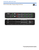
OPERATING INSTRUCTIONS LD-3 Air Attenuation Compensating Line Driver Keep these important operating instructions. Check www.meyersound.com for updates.
DECLARATION OF CONFORMITY ACCORDING TO ISO/IEC GUIDE 22 AND EN 45014 Manufacturer's Name: Meyer Sound Laboratories Inc.
SYMBOLS USED These symbols indicate important safety or operating features in this booklet and on the chassis: ! Dangerous voltages: risk of electric shock Important operating instructions Frame or chassis Protective earth ground Pour indiquer les risques résultant de tensions dangereuses Pour indequer important instructions Masse, châssis Terre de protection Zu die gefahren von gefährliche spanning zeigen Zu wichtige betriebsanweisung und unterhaltsanweisung zeigen Rahmen oder chassis Die schut
iv
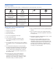
CONTENTS INTRODUCTION How to use this manual Introducing The LD-3 Air Attenuation Compensating Line driver 1 1 1 CHAPTER 1: AC Power Requirements 3 CHAPTER 2: Audio and System Controls 5 Audio Input Atmospheric Correction Temperature Altitude Relative Humidity Array Correction Array Type Array Size The Enter Button Master Input Channels A and B Channels 1-3 (A and B) Outputs Distance Control Insert Switch Insert Inputs Send Outputs Subs A and B Insert Switch Insert Inputs CHAPTER 3: System Design, In
vi
INTRODUCTION INTRODUCTION HOW TO USE THIS MANUAL As you read this manual, you’ll find figures and diagrams to help you understand and visualize what you’re reading. You’ll also find numerous icons that serve as cues to flag important information or warn you against improper or potentially harmful activities. These icons include: A NOTE identifies an important or useful piece of information relating to the topic under discussion. A TIP offers a helpful tip relevant to the topic at hand.
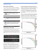
INTRODUCTION The Master Input section provides individual channel Gain adjustment from –12 to +6 dB, an illuminated Mute switch, Signal/Clip indicator, and a switchable High-Pass Filter (0, 80, or 160 Hz) for boundary correction or optimizing crossover to subwoofers. Master environmental controls include Temperature (0° to 45° C), Altitude (switchable in three ranges: 0-800, 800-2200, and 2200+ m) and Relative Humidity (10 to 100%).
CHAPTER 1 CHAPTER 1: AC POWER REQUIREMENTS The LD-3 uses an international standard IEC 320 mains AC inlet. This convenient rear panel receptacle accepts many power cord types for mains outlets used throughout the world. The LD-3 must have the correct power cord for the AC power in the area in which it will be used. The LD-3 operates in two AC voltage ranges: 105 – 125 V and 210 – 250 V, at 50 or 60 Hz (Figure 1.1).
CHAPTER 1 4
CHAPTER 2 CHAPTER 2: AUDIO AND SYSTEM CONTROLS Much more than a system integration tool, the LD-3 line driver uses its sophisticated circuitry to bring consistent and predictable results to any M Series line or curvilinear array design. This chapter will help you understand and harness the power of the LD-3's audio and system controls.
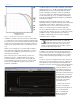
CHAPTER 2 Temperature The green Temperature control allows you to set temperature in 1° increments from 0° to 45° C. A convenient Fahrenheit (F) to Celsius (c) conversion table is located to the bottom left of the Atmospheric Correction section (Figure 2.2).
CHAPTER 2 The Array Correction section (Figure 2.4), lets you set the type of M Series loudspeaker using the Array Type selector switch and the number of cabinets in the array with the Array Size control. NOTE: The firmware and ROM (Read Only Memory) which support the LD-3’s array correction functions are upgradeable in the field. Contact Meyer Sound or visit the Meyer Sound Web site at www.meyersound.com for more information on when this feature and upgrades will be available.
CHAPTER 2 For example, if the Temperature is set to 25° and the Relative Humidity to 40%, press Enter, then change the Temperature to 30°; press Enter again for the LD-3 to register the new temperature. MASTER INPUT CHANNELS A AND B Master input channels A and B (Figure 2.6) are equipped to control a full-range main system. Front Panel Rear Panel These filters are used to optimize integration with subwoofers; in several cases they can augment an array’s headroom by filtering low frequencies out.
CHAPTER 2 NOTE: Although the LD-3 offers a large gain range (-6 to +6 dB) for each output, gain tapering is not recommended for arrays. Adjusting zones with an overall amplitude control for each zone results in the following: 1. 2. 3. Directionality decreases. Low-frequency headroom decreases. The length of the line or curvilinear array column is effectively shortened. Distance Control The green Distance control allows you dial-in the throw from the array on each output channel, from 0 to 150 meters.
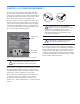
CHAPTER 2 Once the correction changes are enabled, press the Enter button and the LD-3 changes how much correction is needed due to the throw of your M Series line or curvilinear array on the channel. Insert Switch Each output channel utilizes an Insert switch which allows you to add outboard signal processing such as parametric equalization. Figure 2.10 shows the Insert/Return Inputs, as well as the auxiliary output section (Sends), with a Meyer Sound CP-10 complementary phase parametric equalizer.
CHAPTER 2 Insert Switch Each Sub channel utilizes an Insert switch (Figure 2.12) which, when engaged, is useful for driving a sub with a different send or output from a console, or other outboard equipment, if desired. Figure 2.12. The LD-3’s Sub inserts CAUTION: The Sub section’s Insert inputs are not normalized; if the Insert switch is depressed with nothing connected, the channel will be effectively muted.
CHAPTER 2 12
CHAPTER 3 CHAPTER 3: SYSTEM DESIGN, INTEGRATION, AND OPTIMIZATION The LD-3 opens up a number of design and integration scenarios. Its versatility, in conjunction with different M Series loudspeakers and/or subwoofers, gives you the freedom to not only plan for the atmospheric conditions and optimized the array, but to hone the design through quantitative Meyer Sound tools and software.
CHAPTER 3 LOUDSPEAKER/SUBWOOFER INTEGRATION Using the LD-3’s filters helps to easily integrate and optimize your M Series arrays with subwoofers. High-pass filters augment array headroom by removing frequencies near the low end of the loudspeaker's operating range, while low-pass filters can remove unwanted mid-low frequencies reproduced by the subwoofers. NOTE: Full-range signals may be applied to Meyer Sound’s self-powered loudspeakers and subwoofers because they have built-in active crossovers.
CHAPTER 3 NOTE: When loudspeakers and subwoofers are physically separated by more than 4 feet – or delay must be used between them – a measurement system such as SIM (covered in the next section) should be used to determine the correct delay and polarity. SIM® MEASUREMENT SYSTEM Meyer Sound also offers a self-contained design and troubleshooting package: the SIM Measurement System.
CHAPTER 3 16
APPENDIX A APPENDIX A LD-3 Line Driver Specifications ATMOSPHERIC CORRECTION (Affects Output Channels 1-3, both A & B) Temperature 0 to 45° Celsius Relative Humidity 10 to 100% RH Altitude 3 position switch: 0 to 800, 800 to 2200, 2200 and up Distance See “Outputs: Channels 1-3 (A&B)” ARRAY CORRECTION Type M1D, M2D, MILO, M3D, upgradable Remote Setting Array Size 1 to 24 Elements in the array (If set to 1 element, bypasses array correction) MASTER INPUTS Attenuation Control -12 to +6 dB Mute Master mute, c
APPENDIX A INPUT CONNECTORS Master A & B 2 Female XLR; 1 per input channel Insert/Return Sub Input 2 Female XLR; 1 per input channel Channels 1-3 (A&B) 6 Female XLR; 1 per input channel; Insert is Pre-Atmospheric Correction / Post-High Pass Filter/Crossover AUDIO OUTPUTS Type Balanced, cross-coupled simulated transformer topology Impedance 50 Ω balanced (between pins 2 and 3) RF Filter Pins 2 and 3 shunted to chassis via 500 pF capacitance Wiring Pin 1: chassis/earth ground; Pin 2: signal; Pin 3: signal
APPENDIX B APPENDIX B Example Configurations LD-3 IN Channel A SUB OUT CH 1 OUT CH 2 OUT CH 3 OUT IN Channel B SUB OUT CH 1 OUT CH 2 OUT CH 3 OUT Channel A INSERTS IN SUB SENDS OUT Full Range IN CH 1 OUT Post Array IN CH 2 OUT IN CH 3 Post Array Post HPF Channel B INSERTS IN SUB IN CH 1 IN CH 2 IN CH 3 SENDS OUT Full Range OUT Post Array OUT Post Array Post HPF Left Right 19
APPENDIX B LD-3 Left IN Channel A SUB OUT CH 1 OUT CH 2 OUT CH 3 OUT Right IN Channel B SUB OUT CH 1 OUT CH 2 OUT CH 3 OUT Channel A INSERTS IN SUB IN CH 1 SENDS OUT Full Range OUT Post Array IN CH 2 OUT IN CH 3 Post Array Post HPF Channel B INSERTS IN SUB IN CH 1 IN CH 2 IN CH 3 20 SENDS OUT Full Range OUT Post Array OUT Post Array Post HPF
APPENDIX B LD-3 Main Left IN (10) MILO Channel A (10) MILO SUB OUT CH 1 OUT CH 2 OUT CH 3 OUT Right IN Channel B SUB OUT CH 1 OUT CH 2 OUT CH 3 OUT Subwoofer Mono Channel A INSERTS IN SUB SENDS OUT Full Range IN CH 1 OUT Post Array IN CH 2 OUT IN CH 3 Post Array Post HPF Channel B INSERTS IN SUB IN CH 1 IN CH 2 IN CH 3 SENDS OUT Full Range OUT Post Array OUT Post Array Post HPF Digital Delay Digital Delay/EQ 2 In x 6 Out 21
APPENDIX C APPENDIX C LD-3 Signal Flow Diagram LED Signal & Clip Detector MAIN INPUT - 3 + 2 G GREEN / RED CH 1-3 CROSSOVER MASTER LEVEL ESD Absorber EARTH GND/ CHASSIS 1 ARRAY SIZE CORRECTION RF Filter -12 to +6dB EARTH GND/ CHASSIS LED GREEN / RED ESD Absorber 10k EARTH GND/ CHASSIS EARTH GND/ CHASSIS OFF 80 Hz MICRO PROCESSOR ENTER Serial Data Port (Remote Download) 80 Hz 160 Hz 160 Hz EARTH GND/ CHASSIS M1D M2D MILO M3D # OF SPEAKERS SPKR MODEL SEND 2 ESD Absorbers ESD
APPENDIX C ESD Absorber + PUSH-PULL DRIVER POWER OFF MUTE (SHORT) - Post HPF X-Over 2 + 1 G Post Array Correction EARTH GND/ CHASSIS EARTH GND/ CHASSIS SIGNAL & CLIP DETECTOR LED GREEN / RED -6 TO +6 dB - 3 CHANNEL 1 INSERT + 2 PRE-ATMOSPHERIC POST HPF G 1 ESD Absorber ATMOSPHERIC CORRECTION RF Filter EARTH GND/ CHASSIS EARTH GND/ CHASSIS INSERT SWITCH DIFFERENTIAL AMPLIFIER EARTH GND/ CHASSIS - 3 CHANNEL 2 INSERT + 2 PRE-ATMOSPHERIC POST HPF G 1 EARTH GND/ CHASSIS ES
APPENDIX C 24
Meyer Sound Laboratories Inc. 2832 San Pablo Avenue Berkeley, CA 94702 USA T: +1 510 486.1166 F: +1 510 486.8356 techsupport@meyersound.com www.meyersound.com © 2003 Meyer Sound Laboratories Inc.