assembly guide m series MG-M’elodie Multipurpose Grid and Accessories Keep these important assembly instructions. Check www.meyersound.com for updates.
© 2007 Meyer Sound. All rights reserved. MG-M’elodie Multipurpose Grid and Accessories Assembly Guide The contents of this manual are furnished for informational purposes only, are subject to change without notice, and should not be construed as a commitment by Meyer Sound Laboratories Inc. Meyer Sound assumes no responsibility or liability for any errors or inaccuracies that may appear in this manual.
MG-M’elodie multipurpose grid and Accessories CONTENTS This assembly guide provides instructions on how to safely assemble and use the MG-M’elodie multipurpose grid and accessories. In addition to descriptions of the MG-M’elodie grid’s major components, this guide will show how the components work together with examples of common uses. 1. Safety, Regulatory, Inspection & Maintenance Information................................................................................... 4 2.
MG-M’elodie multipurpose grid and Accessories 1. Safety, Regulatory, Inspection & Maintenance Information Please read this Statement carefully and in its entirety. It contains important information regarding safety issues, including guidelines for general safe use of rigging systems as well as advisories on government regulations and liability laws.
MG-M’elodie multipurpose grid and Accessories INSPECTION AND MAINTENANCE The Meyer Sound QuickFly systems are an assembly of mechanical devices, and are therefore subject to wear and tear over prolonged use, as well as damage from corrosive agents, extreme impact, or inappropriate use. Because of the safety issues involved, users must adopt and adhere to a schedule of regular inspection and maintenance. In touring applications, key components must be inspected before each use.
MG-M’elodie multipurpose grid and Accessories 2. THE M’elodie™ GUIDEALINK™ RIGGING SYSTEM M’elodie loudspeakers feature Meyer Sound’s QuickFly® rigging system with rugged, reliable and simple components. QuickFly facilitates deploying the loudspeakers in a variety of applications.
MG-M’elodie multipurpose grid and Accessories A small label on the end frame serves as a guide to pin positions in the GuideALink, to help locate the desired angle as the knob moves up the frame. In the bottom position, the splay angle between cabinets is 0 degrees. As you move the knob upwards, the angle increases to 11 degrees. To stow the link, the knob is moved to the top of the slot.
MG-M’elodie multipurpose grid and Accessories 3. THE MG-M’elodie MULTIPURPOSE GRID The MG-M’elodie multipurpose grid allows multiple M’elodie ultracompact high-power curvilinear array loudspeakers to be flown or ground-stacked in numerous configurations. In flown configurations, the first M’elodie loudspeaker in the array can be connected to the MG-M’elodie grid at 0, -5, or -10 degrees with respect to the grid.
MG-M’elodie multipurpose grid and Accessories MG-M’elodie Multipurpose Grid Dimensions: 28.74 729.89 26.74 679.09 18.25 463.55 16.25 412.75 14.25 361.95 12.25 311.15 22.50 571.50 10.25 260.35 20.50 520.70 8.25 209.55 6.25 158.75 4.25 107.95 2.25 57.15 0 0 Side view of center beam 3.00 76.20 20.00 508.00 MG-M’elodie Multipurpose Grid Weight: 36 lbs (16.33 kg) Meyer Sound Laboratories Inc. www.meyersound.com T: +1 510 486.1166 F: +1 510 486.8356 PN: 05.152.019.
MG-M’elodie multipurpose grid and Accessories 4. Using the MG-M’elodie MULTIPURPOSE GRID to Fly M’elodie Arrays ADJUSTING THE ANGLE BETWEEN THE GRID AND the FIRST M’ELODIE The MG-M’elodie has four captive grid links; each grid link has three positions. In flown configurations, the first M’elodie loudspeaker in the array can be connected to the MG-M’elodie grid at 0, -5, and -10 degrees depending on the combination of the grid links position (see Table 1).
MG-M’elodie multipurpose grid and Accessories ROTATING THE GRID TO ACHIEVE MORE DOWNTILT OR UPTILT The MG-M’elodie grid can be rotated to fly M’elodie loudspeakers in two positions with respect to the grid. The “rear flown” position (M’elodie is closer to the rear of the grid) is most useful for achieving a few degrees more of uptilt and it is labeled “Maximum Up-tilt” on the grid.
MG-M’elodie multipurpose grid and Accessories MG-M’elodie Pickup Configurations The MG-M’elodie grid can accommodate a variety of pickup configurations using its four side pickup points and/or the nine center pickup points. When possible, it is recommended to use front and rear pickup points to change the tilt of the grid and the array by using the front and rear motors. CAUTION: Always use properly rated rigging hardware. The use of 5/8" shackles for the MG-M’elodie grid’s pickup points is recommended.
MG-M’elodie multipurpose grid and Accessories In addition, the MG-M’elodie can be suspended from a single motor. However, limitations like the load rating of the motor and the pickup point in the ceiling “above the hook” need to be taken into consideration. Also, it becomes more difficult to change the tilt angle of the grid. NOTE: The design of the MG-M’elodie allows the use of any pickup configuration without affecting the load rating.
MG-M’elodie multipurpose grid and Accessories MAPP ONLINE PRO MAPP Online Pro is a powerful acoustical prediction software that is an invaluable tool when designing a system. This software is a cross-platform, Java-based application for accurately predicting the coverage pattern, frequency response, impulse response, and maximum SPL output of single or arrayed Meyer Sound loudspeakers.
MG-M’elodie multipurpose grid and Accessories The magenta line indicates the center of gravity of the array Meyer Sound Laboratories Inc. www.meyersound.com T: +1 510 486.1166 F: +1 510 486.8356 Zoomed view, showing pickup points PN: 05.152.019.
MG-M’elodie multipurpose grid and Accessories Load Ratings Overview All of the load ratings for the MG-M’elodie grid in this assembly guide take the following into consideration. Prerequisite Conditions The following conditions must be met to achieve the load ratings shown in Table 2: Any combination of pickup points can be used. If a bridle is used between pickup points on the MG-M’elodie, the angle of the bridle at the apex is no greater than 90 degrees.
MG-M’elodie multipurpose grid and Accessories Table 2.
MG-M’elodie multipurpose grid and Accessories 5. Using the MG-M’elodie Grid to Ground-Stack M’elodie Arrays In addition to its suspending capabilities, the MG-M’elodie grid forms a secure base for ground-stacking. For groundstacking, secure the GuideALinks in the bottom M’elodie enclosure to the MG-M’elodie grid using the red button (5/16" x 0.875") quick-release pins. CAUTION: Always use red button pins (5/16" x 0.875") or blue button pins (5/16" x 1.
MG-M’elodie multipurpose grid and Accessories When the M’elodie loudspeaker is pinned to the MG-M’elodie grid, there are two positions for the rear link in the grid: 0° Position: Allows the first M’elodie to be angled from 0 to +5 degrees (uptilt) Table 3a.
MG-M’elodie multipurpose grid and Accessories 6. MTF-MICA/M’elodie transition Frame The MTF-MICA/M’elodie transition frame allows numerous configurations for transitioning between MICA and 600-HP to M’elodie in a single flown or ground-stacked array. List of Contents: MTF-MICA/-M’elodie Transition Frame (Part #40.152.080.01) Required for use with M’elodie loudspeaker(s) 134.024 5/16” .625” 134.025 5/16” .875” Meyer Sound Laboratories Inc. www.meyersound.com Qty Part Number Description 1 40.152.
MG-M’elodie multipurpose grid and Accessories MTF-MICA/M’elodie Transition Frame Dimensions: 43.59 [1107.26 mm] 41.55 [1055.24 mm] 20.25 [514.35 mm] 2.50 [63.50 mm] MTF-MICA/M’elodie Transition Frame Weight: 54 lbs (24.50 kg) Load Ratings The load ratings for the MTF-MICA/M’elodie in this assembly guide take the following into consideration. Prerequisite Conditions The following conditions must be met to achieve the load ratings shown in Table 4.
MG-M’elodie multipurpose grid and Accessories Table 4. MTF-MICA/M’elodie load ratings Factor of Safety Total Suspended Weight M’elodie Equivalent Cabinets Maximum Grid Tilt 5:1 7:1 868 lbs (393.7 kg) 620 lbs (281.2 kg) 14 10 -45º to +45º -45º to +45º NOTE: The transition frame will be adequate to withstand an array of 12 M’elodies (744 lbs, 337.
MG-M’elodie multipurpose grid and Accessories Using the MTF-MICA/MG-M’elodie Transition Frame to Fly M’elodie Underneath a MICA Array When using M’elodie enclosures as downfill in a MICA array, the MTF-MICA/M’elodie transition frame is used between the lowest MICA and the first M’elodie in the combined array. Please note that the transition frame receives the AlignALinks from MICA and the M’elodie is attached using MTF-M’elodie links.
MG-M’elodie multipurpose grid and Accessories MICA-MTF frame angle This angle can be varied using MICA’s rear link positions to achieve 0, -0.5, -1, -1.5, -2, -2.5, -3, and -4 degrees. MICA and MTF frame at 0 degrees (left) and -4 degrees (right) In addition, using the extended position on the MICA’s front link and positions 0-3 on the rear link, you can achieve from -7 to -10 degrees between the MICA and the MTF frame.
MG-M’elodie multipurpose grid and Accessories The resultant angle is the sum of the angles between the MICA and the MTF frame and the MTF frame and the M’elodie underneath. Please refer to Table 5. Positions to achieve -9, -15, and -20 degrees between MICA and M’elodie Table 5. Possible angles, MICA/M’elodie configuration* MICA-MTF angle MTF-M’elodie angle Resultant MICAM’elodie angle 0 -0.5 0 0 0 -0.5 -1 0 -1 -1.5 -2 -2.5 -3 -4 0 -0.5 -1 -1.5 -2 -2.5 -3 -8.5 -4 0 -0.5 -1 -1.5 -2 -2.5 -3 -8.
MG-M’elodie multipurpose grid and Accessories Using the MTF-MICA/MG-M’elodie Transition Frame to Fly M’elodie Underneath a 600-HP Array When using full-range combined arrays with 600-HP subwoofers at the top of the array and M’elodie enclosures below, the MTF-MICA/M’elodie transition frame is used between the lowest 600-HP subwoofer and the first M’elodie in the combined array.
MG-M’elodie multipurpose grid and Accessories 600-HP-MTF frame angle This angle can be varied in increments of 3 degrees using the 600-HP’s rear link positions to achieve 0, 3, 6, 9, 12, and 15 degrees. 600-HP and MTF frame at 0 degrees (left) and +15 degrees (right) In addition, using the extended position on the 600-HP’s front link and position 0 on the rear link you can achieve -3 degrees between the 600-HP and the MTF frame. 600-HP and MTF frame at -3 degrees Meyer Sound Laboratories Inc. www.
MG-M’elodie multipurpose grid and Accessories MTF frame-M’elodie angle There are three possible angles: 0 , -5, and -10 degrees, which can be achieved by inserting the connecting links into the lower or upper holes of the frame. MTF frame and M’elodie at 0, -5, and -10 degrees (right) The resultant angle is the addition of the angles between the 600-HP and the MTF frame and the MTF frame and the M’elodie underneath. See Table 6 on the following page.
MG-M’elodie multipurpose grid and Accessories Table 6. Possible angles, 600-HP/Melodie flown configuration* 600-HP-MTF angle MTF-M’elodie angle -3 0 -3 3 0 6 -3 3 9 0 6 12 3 9 15 6 12 9 15 12 15 -10 -10 -5 -10 -5 -10 0 -5 -10 0 -5 -10 0 -5 -10 0 -5 0 -5 0 0 Resultant 600-HP/ M’elodie angle -13 -10 -8 -7 -5 -4 -3 -2 -1 0 1 2 3 4 5 6 7 9 10 12 15 Caution: Do not exceed the maximum rated weight underneath the MTF-MICA/M’elodie transition frame.
MG-M’elodie multipurpose grid and Accessories Using the MTF-MICA/MG-M’elodie Transition Frame to Ground-Stack M’elodie on Top of a 600-HP Array When using full-range combined arrays with 600-HP subwoofers ground-stacked at the bottom of the array and M’elodie enclosures above, the MTF-MICA/M’elodie transition frame is used between the top 600-HP subwoofer and the first M’elodie in the combined array.
MG-M’elodie multipurpose grid and Accessories M’elodie-MTF frame angle This angle can be continuously varied in 1-degree increments by inserting the rear M’elodie link in the top rear hole of the frame. The top position on the M’elodie rear link (labeled 0) will give -5 degrees (downtilt) and the hole one up from the bottom position (labeled 10) will give +6 degrees (uptilt).
MG-M’elodie multipurpose grid and Accessories The resultant angle is the addition of the angles between the M’elodie and the MTF frame and the MTF frame and the 600-HP underneath. See Table 7. Positions to achieve +10 and -11.5 degrees between M’elodie and 600-HP Caution: It is recommended to use the MG-MICA multipurpose grid as a base for the 600-HP to form a secure base. Caution: Up to four (4) M’elodie loudspeakers can be easily ground-stacked on top of two (2) 600-HP subwoofers.
MG-M’elodie multipurpose grid and Accessories Table 7. Possible angles, M’elodie/600-HP ground-stacked configuration* M’elodie-MTF Angle MTF-600-HP Angle -5 -4 -3 -2 -1 0 1 -5 2 -4 3 -3 4 -2 5 -1 6 0 1 2 3 4 5 6 3 4 5 6 -6.5 -6.5 -6.5 -6.5 -6.5 -6.5 -6.5 0 -6.5 0 -6.5 0 -6.5 0 -6.5 0 -6.5 0 0 0 0 0 0 0 4 4 4 4 Resultant M’elodie600-HP angle -11.5 -10.5 -9.5 -8.5 -7.5 -6.5 -5.5 -5 -4.5 -4 -3.5 -3 -2.5 -2 -1.5 -1 -0.
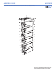
MG-M’elodie multipurpose grid and Accessories 7. MCF-M’elodie Caster Frame The MCF-M’elodie caster frame allows you to transport stacks of up to five (5) M’elodie enclosures. The M’elodie GuideALinks connect the enclosures securely to the frame, allowing the convenient transport of straight or splayed stacks of M’elodie. The steel frame surrounding the board facilitates the use of forklifts. NOTE: Always use the included 5/16" x 0.
MG-M’elodie multipurpose grid and Accessories Whether you’re deploying or striking an array, the MCF-M’elodie can temporarily support the entire array — making it easy to assemble or disassemble the array in stacks of up to five (5) M’elodies. Caution: Do not exceed five (5) M’elodie cabinets high to avoid tipping over the stack.
MG-M’elodie multipurpose grid and Accessories The M’elodie GuideALinks allow multiple transport angles with the MCF-M’elodie caster frame. Use the 5 position on the M’elodie rear GuideALink to get the first M’elodie with respect to the caster frame at 0 degrees. This setting is preferred when all M’elodies are at 0 degrees. Use the 0 position to downtilt the first M’elodie with respect to the caster frame, to compensate if the rest of the M’elodies in the stack have angles.
MG-M’elodie multipurpose grid and Accessories Tip: The MG-M’elodie can travel installed on top of a M’elodie stack. Caution: The use of severe angles between M’elodies makes the stack less stable. If an MGM’elodie grid is being transported on top of the stack, set all M’elodies at 0 degrees with respect to the caster frame to avoid tipping over the stack.
MG-M’elodie multipurpose grid and Accessories 8. The MUB-M’elodie Multipurpose U-Bracket The MUB-M’elodie multipurpose U-bracket is primarily designed to support and aim a single M’elodie loudspeaker in a floor- or ceiling-mounted configuration (it can also be mounted on a pole mount). However, it is robust and versatile enough for stacking and flying arrays of up to three M’elodie loudspeakers. Multiple mounting holes provide maximum flexibility for the loudspeaker’s tilt.
MG-M’elodie multipurpose grid and Accessories MUB-M’elodie Multipurpose U-Bracket Dimensions: 28.66 [727.89mm] 26.86 [682.24mm] 11.86 [301.31mm] 11.50 [292.10mm] 26.62 [676.15mm] 24.00 [609.60mm] 4.87 [123.70mm] 8.50 [215.90mm] MUB-M’elodie Multipurpose U-Bracket Weight: 13 lbs (5.90 kg) Meyer Sound Laboratories Inc. www.meyersound.com T: +1 510 486.1166 F: +1 510 486.8356 PN: 05.152.019.
MG-M’elodie multipurpose grid and Accessories Load Ratings CAUTION: When flying an array from the MUB-M’elodie U-bracket, it must always be supported by mounting holes on the end of the bracket. The 1/4" center holes are only to be used with a stand mount adaptor. CAUTION: Always use mounting hardware that is appropriate for the surface where the MUB-M’elodie multipurpose U-bracket will be installed, and that has been rated to meet or exceed the weight of the installed loudspeakers.
MG-M’elodie multipurpose grid and Accessories MUB-M’elodie Angle Settings One end of the MUB-M’elodie U-bracket has seven holes to allow for a range of angles for the attached M’elodie cabinet. The U-bracket holes align with those in the M’elodie. Red quick-release pins — included with each M’elodie loudspeaker — are used to secure the M’elodie (two per side) to the MUB-M’elodie U-bracket.
MG-M’elodie multipurpose grid and Accessories MUB-M’elodie Floor-Mount Configurations The MUB-M’elodie U-bracket can be mounted to a floor to aim a single M’elodie loudspeaker, or it can be used for stacking up to three (3) M’elodie loudspeakers. The tilt of the M’elodie attached to the MUB-M’elodie U-bracket can be from -5 to +15 degrees in 2.5-degree increments.
MG-M’elodie multipurpose grid and Accessories MUB-M’elodie Ceiling-Mount Configurations The MUB-M’elodie U-bracket can be mounted to a ceiling with up to three (3) M’elodie loudspeakers attached. The tilt of the M’elodie attached to the MUB-M’elodie U-bracket can be from +5 to -15 degrees in 2.5-degree increments. The MUB-M’elodie U-bracket must be safely secured to the ceiling with fasteners placed in the bracket’s four 1/4" corner holes.
MG-M’elodie multipurpose grid and Accessories MUB-M’elodie on a Pole-Mount Stand You can use the MUB-M’elodie U-bracket with a third-party pole adapter (available from Ultimate Support, for example) to mount one (1) M’elodie loudspeaker on a pole. The tilt of the M’elodie attached to the MUB-M’elodie U-bracket can be from -5 to +15 degrees in 2.5-degree increments. The MUB-M’elodie U-bracket is secured to the pole adapter with fasteners placed in the bracket’s two 1/4" center holes.
MG-M’elodie multipurpose grid and Accessories MUB-M’elodie Flown Configurations The MUB-M’elodie supports flown arrays of up to three (3) M’elodie loudspeakers. The tilt of the M’elodie attached to the MUB-M’elodie U-bracket can be from +5 to -15 degrees in 2.5-degree increments. The MUB-M’elodie U-bracket can be clamped to a truss using its two 1/2" center holes on the top of the bracket, or the MUB-M’elodie can be suspended with four eyebolts attached to the bracket’s four corner holes.
MG-M’elodie multipurpose grid and Accessories APPENDIX: Assembling an Array of M’elodies to the MG-M’elodie Grid 1. Lay the MG-M’elodie grid on the floor or road trunk in the approximate location where the rigging point(s) have been established and the motor(s) hung.
MG-M’elodie multipurpose grid and Accessories Caution: If the links are not stowed as described in Step 8, you run the risk of denting or penetrating the wood on the top loudspeaker in the stack by hitting it with an extended link. 12. Pin the front links first. Position and pin the rear links of the suspended M’elodie loudspeaker to the desired angle. “Bump” the motors to lower the rear GuideALinks into the link pockets of the M’elodie to be attached, and pin. 13.
Meyer Sound Laboratories Inc. 2832 San Pablo Avenue Berkeley, CA 94702 www.meyersound.com T: +1 510 486.1166 F: +1 510 486.8356 © 2007 Meyer Sound Laboratories Inc. 05.152.019.