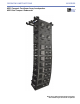
OPERATING INSTRUCTIONS M SERIES M2D Compact Curvilinear Array Loudspeaker M2D-Sub Compact Subwoofer Keep these important operating instructions. Check www.meyersound.com for updates.
DECLARATION OF CONFORMITY ACCORDING TO ISO/IEC GUIDE 22 AND EN 45014 Manufacturer's Name: Meyer Sound Laboratories Inc. Manufacturer's Address: 2832 San Pablo Avenue Berkeley, CA 94702-2204, USA Declares that the products Product Name: M2D and M2D-Sub Loudspeakers Product Options: All Safety: EMC: IEC 60065:1998 EN 60065:1998 UL 6500/09.99 CAN/CSA E60065-00 EN 55103-1: 1997 emission(1) EN 55103-2: 1997 immunity(2) This device complies with EN 55103-1 & -2.
SYMBOLS USED These symbols indicate important safety or operating features in this booklet and on the chassis: Dangerous voltages: risk of electric shock Important operating instructions Frame or chassis Protective earth ground Pour indiquer les risques résultant de tensions dangereuses Pour indequer important instructions Masse, châssis Terre de protection Zu die gefahren von gefährliche spanning zeigen Zu wichtige betriebsanweisung und unterhaltsanweisung zeigen Rahmen oder chassis Die schutze
SAFETY SUMMARY English - - - - - - To reduce the risk of electric shock, disconnect the loudspeaker from the AC mains before installing audio cable. Reconnect the power cord only after making all signal connections. Connect the loudspeaker to a two-pole, three-wire grounding mains receptacle. The receptacle must be connected to a fuse or circuit breaker. Connection to any other type of receptacle poses a shock hazard and may violate local electrical codes.
CONTENTS INTRODUCTION How to Use this Manual Introducing the M2D and M2D-Sub Loudspeakers 1 1 1 CHAPTER 1: Power Requirements 3 AC Power AC Power Distribution Power Connector Wiring Voltage and Current Requirements M2D Voltage Requirements M2D Current Requirements M2D-Sub Voltage Requirements M2D-Sub Current Requirements 3 3 4 5 5 5 6 6 CHAPTER 2: Amplification and Audio Audio Input M2D Interconnections M2D Amplification M2D Limiting M2D Amplifier Cooling System Optional Fan Assembly Kit M2D-Sub Inter
Adding a Line Driver Engaging the Lo-Cut Filter Using the LD-3 Digital Signal Processors Using the 650-P with the M2D CHAPTER 5: System Design and Integration tools Meyer Sound MAPP Online® SIM® Measurement System Source Independent Measurement Technique Applications CHAPTER 6: QuickFly® Rigging MG-2D Multipurpose Grid MG-1D Multipurpose Grid APPENDIX A Troubleshooting APPENDIX B M2D Specifications M2D-Sub Specifications vi 20 20 21 21 21 23 23 24 24 24 25 25 26 27 27 29 29 31
INTRODUCTION INTRODUCTION HOW TO USE THIS MANUAL As you read this manual, you’ll find figures and diagrams to help you understand and visualize what you’re reading. You’ll also find numerous icons that serve as cues to flag important information or warn you against improper or potentially harmful activities. These icons include: A NOTE identifies an important or useful piece of information relating to the topic under discussion. A TIP offers a helpful tip relevant to the topic at hand.
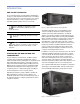
INTRODUCTION With an operating frequency range of 28 Hz to 160 Hz, the dual 15-inch M2D-Sub loudspeaker complements the M2D loudspeaker in reinforcement applications requiring extended low-frequency headroom. The M2D-Sub loudspeaker affords 138 dB SPL peak output capability. It employs two Meyer Sound ferrofluid cooled, back-vented drivers each featuring a 4-inch voice coil with a lightweight neodymium magnet structure. Each driver is rated to handle 1200 AES watts.
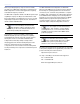
CHAPTER 1 CHAPTER 1: POWER REQUIREMENTS The M2D and M2D-Sub loudspeakers represent advanced technology with equally advanced power capabilities. Understanding power distribution, voltage and current requirements, as well as electrical safety issues, is critical to their safe operation and deployment. AC POWER � �������� The M2D and M2D-Sub ��� loudspeakers use a PowerCon® 3-pole AC mains system with locking connectors to prevent accidental disconnection or a multipin VEAM™ male power connector (Figures 1.
CHAPTER 1 Figure 1.4 shows a sample three-phase AC distribution system, with the load between loudspeakers distributed among the three phases and all of the loudspeakers connected to common neutral and earth ground points.
CHAPTER 1 VOLTAGE AND CURRENT REQUIREMENTS M2D Current Requirements M2D Voltage Requirements Each M2D loudspeaker requires approximately 3 A rms max at 115 volts AC for proper operation. This allows up to five M2D loudspeaksers to be powered from one 15 A breaker. The M2D loudspeaker operates safely and without audio discontinuity if the AC voltage stays within the operating window of 90 to 265 volts AC, at 50 to 60 Hz.
CHAPTER 1 M2D-Sub Voltage Requirements The M2D-Sub loudspeaker operates safely and without audio discontinuity if the AC voltage stays within either of two operating windows at 50 or 60 Hz: 85 to 134 volts If the M2D-Sub loudspeaker shuts down due to either low or high voltage, its power supply automatically turns on after three seconds if the voltage has returned to either normal operating window.
CHAPTER 1 NOTE: For best performance, the AC cable voltage drop should not exceed 10 volts, or 10 percent at 115 volts and 5 percent at 230 volts. Make sure that even with the AC voltage drop the AC voltage always stays in the operating windows. The minimum electrical service amperage required by the M2D-Sub system is the sum of each loudspeaker’s maximum continuous rms current. An additional 30 percent above the minimum amperage is recommended to prevent peak voltage drops at the service entry.
CHAPTER 1 8
CHAPTER 2 CHAPTER 2: AMPLIFICATION AND AUDIO The M2D and M2D-Sub loudspeakers use sophisticated amplification and protection circuitry to produce consistent and predictable results in any system design. This chapter will help you understand and harness the power of the M2D and M2D-Sub amplifier and audio systems. The rear panels of the M2D and M2D-Sub loudspeakers (Figures 2.1 and 2.2) provide AC connection, audio input, loop out and an interface to the RMS communications module.
CHAPTER 2 When driving multiple loudspeakers in an array, make certain that the source device can drive the total load impedance presented by the paralleled input circuit of the array. The audio source must be capable of producing a minimum of 20 dB volts (10 volts rms into 600 ohms) in order to produce the maximum peak SPL over the operating bandwidth of the loudspeaker.
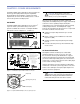
CHAPTER 2 ���� �������� high-frequency LED (yellow) low-frequency LED (yellow) Figure 2.4. The M2D loudspeaker’s limit LED indicators �� ��� ��� �� �� � �� �� �� ��� �� If the limit LEDs are on for no longer than two seconds, ������� and off for at least one second, the M2D loudspeaker is performing within its acoustical specifications and operating at a normal temperature.
CHAPTER 2 M2D-SUB AMPLIFICATION The M2D-Sub loudspeaker is powered by the Meyer Sound HP-2/M2D-Sub amplifier, a high-power twochannel amplifier. The amplifier utilizes complementary MOSFET output stages (class AB/H) capable of delivering 2250 watts total. All the specific functions for the M2DSub loudspeaker such as crossover points, frequency and phase response, and driver protection are determined by the control card installed inside the amplifier.
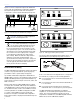
CHAPTER 2 M2D-SUB AMPLIFIER COOLING SYSTEM The M2D-Sub loudspeaker uses a forced-air cooling system with two fans to prevent the amplifier module from overheating. The fans draw air in through ducts on the front of the cabinet, over the heatsink, and out the rear of the cabinet (Figure 2.6). Because dust does not accumulate in the amplifier circuitry, its lifespan is increased significantly. The front grille helps to filter the air and should always be in place during operation.
CHAPTER 2 14
CHAPTER 3 CHAPTER 3: RMS REMOTE MONITORING SYSTEM The M2D and M2D-Sub loudspeakers are fitted standard with an RMS communication module installed in the rear of the loudspeaker. The RMS real-time networked monitoring system connects Meyer Sound self-powered loudspeakers with a Windows-based PC at the sound mix position or other remote location. Optional RMS software delivers extensive status and system performance data directly to you from every installed loudspeaker.
CHAPTER 3 Service Button USER INTERFACE Pressing the Service button will display an icon on the corresponding loudspeaker display icon on the RMS screen. When used in combination with the Reset button, the communications module will be decommissioned from the network and the red Service LED will blink. The optional RMS software features an intuitive, graphical user interface.
CHAPTER 4 CHAPTER 4: LINE ARRAYS AND SYSTEM INTEGRATION A line array, in the most basic sense, is a group of closely spaced loudspeakers arrayed in a straight line, operating with equal amplitude and in phase. Although line arrays have been used since the 1950s, line array systems that provide full bandwidth directivity are relatively new to the sound reinforcement industry. HOW LINE ARRAYS WORK Line arrays achieve directivity through constructive and destructive interference.
CHAPTER 4 Horizontal Coverage. Horizontal coverage for a single array can be considered constant regardless of the number of array elements or the angles between them. TIP: The angle between two or more line arrays can also be changed to meet additional design requirements (for example, wall reflections).
CHAPTER 4 Figures 4.1 shows a series of MAPP Online predictions based on an example M2D system design. In this case, small vertical splay angles on the upper part of the array are used to cover longer distances, while greater angles are used in the lower elements to increase vertical coverage for shorter distances. The block diagram (Figure 4.2) shows one method of driving this example array, along with additional fill loudspeakers and subwoofers (not in the MAPP Online predictions).
CHAPTER 4 In addition, the use of high-pass filters to drive an M2D system with the M2D-Sub flattens overall frequency response and slightly increases M2D headroom in the lowest end of its usable spectrum. acoustical conditions. If the gains are adjusted to the same level, the combined response is identical to a daisy-chain configuration with a rise in level on the overlapping range. Meyer Sound makes available three different line drivers.
CHAPTER 4 Table 4.3: LD-1A, LD-2 and LD-3 (LD-3 at 160 Hz) “Lo-Cut Filter” Parameters Using the LD-3 In addition to the 160 Hz high-pass filter on the LD-3, the LD-3 compensating line driver provides additional filtering capabilities to help you further fine-tune an M2D/M2D-Sub system. Table 4.
CHAPTER 4 Table 4.4: M2D and 650-P (650-P set to pin 2 positive) frequency response results with LD-1A, LD-2 and LD-3 (160 Hz filter) Lo-Cut ø Reverse Switch Result Off Off Flat response (small rise on 70 Hz -160 Hz area), -6 dB sub gain recommended* Engaged Engaged Very flat response, -6 dB sub gain recommended* * The 650-P subwoofer is +6 dB more sensitive than the M2D and M2D-Sub loudpspeakers.
CHAPTER 5 CHAPTER 5: SYSTEM DESIGN AND INTEGRATION TOOLS Meyer Sound offers two comprehensive tools to assist you with the acoustical and functional requirements of system design and optimization. This chapter introduces you to the Meyer Sound MAPP Online acoustical prediction program, and the SIM audio analyzer, a robust instrumentation package for system measurement, analysis, and more.
CHAPTER 5 SIM MEASUREMENT SYSTEM Applications The SIM audio analyzer is a measurement and instrumentation system including a selection of hardware and software options, microphones and accessory cables. The SIM analyzer is optimized for making audio frequency measurements of an acoustical system with a resolution of up to 1/24 of an octave; the high resolution enables you to apply precise electronic corrections to adjust system response using frequency and phase (time) domain information.
CHAPTER 5 CHAPTER 6: QUICKFLY RIGGING The M2D and M2D-Sub loudspeakers feature Meyer Sound’s QuickFly rigging system with rugged, reliable and deceptively simple components that remain captive, in transit. QuickFly rigging facilitates constructing rigid, ground-stacked or flown M2D-Sub arrays, and eases integration of M2D-Sub and M2D loudspeakers in unitary, full-range curvilinear arrays. This chapter gives an overview of M2D and M2D-Sub rigging accessories.
CHAPTER 5 The MG-2D grid provides additional functionality, including transitioning to an M2D or M2D-Sub array from the bottom of a/an: M3D or M3D-Sub loudspeaker (MTK-2D transition kit required); or MILO loudspeaker (MTB-2D/M transition bar kit required) MG-1D Multipurpose Grid The MG-1D multipurpose grid (Figure 6.4) was originally designed to allow M1D and M1D-Sub loudspeakers to be flown or ground stacked.
APPENDIX A APPENDIX A TROUBLESHOOTING This section contains possible solutions to some common problems encountered by M2D and M2D-Sub loudspeaker users and is not intended to be a comprehensive troubleshooting guide. The On/Temp. LED (Active LED on M2D-Sub) does not illuminate and there is no audio. 1. Make sure the AC power cable is the correct type for the regional voltage and that it is securely connected to the AC inlet, then unplug and reconnect the AC cable. 2.
APPENDIX A 28
APPENDIX B APPENDIX B M2D SPECIFICATIONS ACOUSTICAL Note: The low-frequency power response of the system will increase according to the length of the array. Operating frequency range 60 Hz - 16 kHz Note: Recommended maximum operating frequency range. Response depends upon loading conditions and room acoustics. Frequency response 70 Hz - 14 kHz ±4 dB Note: Free field, measured with 1/3 octave frequency resolution at 4 meters.
APPENDIX B RF filter Common mode: 425 kHz; Differential mode: 142 kHz TIM filter <80 kHz, integral to signal processing Nominal input sensitivity 0 dBV (1 V rms, 1.4 V pk) continuous is typically the onset of limiting for pink noise and music. Input level Audio source must be capable of producing a minimum of +20 dBV (10 V rms, 14 V pk) into 600 ohms in order to produce maximum peak SPL over the operating bandwidth of the loudspeaker.
APPENDIX B M2D-SUB SPECIFICATIONS ACOUSTICAL Note: The low-frequency power response of the system will increase according to the length of the array. Operating frequency range 28 Hz - 160 Hz Note: Recommended maximum operating frequency range. Response depends upon loading conditions and room acoustics. Frequency response 30 Hz - 140 Hz ±4 dB Note: Free field, measured with 1/3 octave frequency resolution at 4 meters.
APPENDIX B Input level Audio source must be capable of producing a minimum of +20 dBV (10 V rms, 14 V pk) into 600 ohms in order to produce maximum peak SPL over the operating bandwidth of the loudspeaker. AMPLIFIERS Amplifier type Two-channel complementary MOSFET output stages (class AB/H) Output power 2250 W total Note: Wattage rating is based on the maximum unclipped burst sine-wave rms voltage the amplifier will produce into the nominal load impedance — both channels 67 V rms (95 V pk).
Meyer Sound Laboratories, Inc. 2832 San Pablo Avenue Berkeley, CA 94702 USA T: +1 510 486.1166 F: +1 510 486.8356 techsupport@meyersound.com www.meyersound.com © 2004 Meyer Sound Laboratories, Inc. All Rights Reserved 05.112.012.