ASSEMBLY GUIDE MTG-1100 Top Grid and Rigging Accessories Keep these important operating instructions. Check www.meyersound.com for updates.
EC DECLARATION OF CONFORMITY within the meaning of the EC Machine Directive 2006/42/EC Product Identification Product Name / Cat. Number: MRK-1100 Rigging Kit / 40.220.027.01 Product Name / Cat. Number: MTG-1100 Top Grid / 40.220.030.01 Brand: Meyer Sound Laboratories Batch / Serial Nr: See batch or serial number on item. For use with 1100-LFC series loudspeaker factory rigging.
CONTENTS Chapter 1: Introduction How to Use This Manual Safety, Regulatory, Inspection & Maintenance Information Chapter 2: 1100-LFC Groundstacks and Cardioid Arrays Groundstacking 1100-LFC Loudspeakers 1100-LFC Cardioid Arrays Chapter 3: MRK-1100 Rigging Kit MRK-1100 Rigging Kit Contents Installing the MRK-1100 Rigging Kit 1100-LFC GuideALinks 5 5 5 9 9 10 11 11 12 13 Chapter 4: MTG-1100 Top Grid 15 MTG-1100 Top Grid Load Ratings 17 Chapter 5: MTG-1100 Pickup Configurations Two Pickup Points Thr
CONTENTS iv
CHAPTER 1: INTRODUCTION HOW TO USE THIS MANUAL Make sure to read these operating instructions in their entirety before configuring a loudspeaker system with 1100-LFC loudspeakers. In particular, pay close attention to material related to safety issues. As you read these operating instructions, you will encounter the following icons for notes, tips, and cautions: NOTE: A note identifies an important or useful piece of information relating to the topic under discussion.
CHAPTER 1: INTRODUCTION All load ratings and other specifications given in this manual are the result of accepted engineering practice and careful testing. However, such specifications and ratings are subject to change. USERS SHOULD CHECK THE QUICKFLY SECTION OF THE MEYER SOUND WEBSITE AT www.meyersound.com OR CONTACT TECHNICAL SUPPORT AT REGULAR INTERVALS TO CHECK FOR UPDATED OR REVISED INFORMATION.
MG-MINA GRID ASSEMBLY GUIDE Annual Comprehensive Examination and Test Program In addition to routine checks on the road for touring systems, Meyer Sound also recommends a careful, comprehensive system examination and testing “at home” in the warehouse or other appropriate location at regular intervals.
CHAPTER 1: INTRODUCTION 8
CHAPTER 2: 1100-LFC GROUNDSTACKS AND CARDIOID ARRAYS GROUNDSTACKING 1100-LFC LOUDSPEAKERS 1100-LFCs can be groundstacked up to four units high, with or without the MRK-1100 rigging kit. Protective, plastic skids are included on the bottom of the 1100-LFC cabinet that securely align with the slots on the cabinet top. Units can be stacked normally or reversed for cardioid configurations. When groundstacking 1100-LFCs, make sure the skids for each unit align with the slots in the cabinet tops.
CHAPTER 2: 1100-LFC GROUNDSTACKS AND CARDIOID ARRAYS 1100-LFC CARDIOID ARRAYS The 1100-LFC low-frequency control element is defined by its sonic linearity in reproducing low-frequency transients at high, continuous output levels with very low distortion. This ultra low distortion, coupled with exceptional headroom and optimized rigging options, makes the 1100-LFC ideal for low-frequency directional applications for large-scale tours and installations.
CHAPTER 3: MRK-1100 RIGGING KIT The optional MRK-1100 rigging kit allows the 1100-LFC to be flown from the MTG-1100 top grid. The rigging kit is available as a factory-installed option or as a field upgrade and uses rugged GuideALinks and intuitive quick-release pins to securely link adjacent loudspeakers in groundstacked and flown array configurations. MRK-1100 RIGGING KIT CONTENTS The MRK-1100 rigging kit includes the following components: PN 40.220.027.01 Quantity Part Number Item 4 45.207.126.
CHAPTER 3: MRK-1100 RIGGING KIT INSTALLING THE MRK-1100 RIGGING KIT To install the MRK-1100 rigging kit: 1. Use a 7/32-inch hex wrench to remove the 16 3/8-inch flathead socket bolts from the 1100-LFC (8 on each side of the cabinet). 2. Apply 1 or 2 drops of Loctite to each 3/8-inch flathead socket bolt. 3. Secure the four rigging bars to the 1100-LFC cabinet with the 3/8-inch flathead socket bolts. Orient the rigging bars with the GuideALinks up and the GuideALink knobs facing away from the cabinet.
MG-MINA GRID ASSEMBLY GUIDE 1100-LFC GUIDEALINKS When equipped with the MRK-1100 rigging kit, the 1100-LFC includes four captive GuideALinks that link to adjacent units in flown and groundstacked arrays. Located at the top corners of the cabinet, the GuideALinks extend up and into the link slots of the cabinet above it (or into the link slots of the MTG-1100 top grid). The links extend and retract with recessed knobs and are secured with quick-release pins.
CHAPTER 3: MRK-1100 RIGGING KIT When linking 1100-LFCs, two quick-release pins are required for each GuideALink: one to secure the link in the bottom unit, and one to secure the link to the top (linked) unit. Eight 1/2 x 1.25-inch quick-release pins (blue) are included with the MRK-1100 rigging kit. Loudspeakers are linked at a fixed splay angle of 0 degrees.
CHAPTER 4: MTG-1100 TOP GRID The MTG-1100 top grid flies 1100-LFC arrays of up to 12 cabinets at a 7:1 safety ratio, or up to 16 cabinets at a 5:1 safety ratio. The grid accommodates a variety of pickup configurations with six pickup points, three each on the front and rear of the grid. The grid also includes 0.28-inch, center attachment points that accommodate brackets and adapters for lasers and inclinometers.
CHAPTER 4: MTG-1100 TOP GRID TIP: The MTG-1100 top grid can travel installed on top of 1100-LFC stacks. TIP: The MTG-1100 top grid includes 0.28-inch, center attachment points that accommodate brackets and adapters for lasers and inclinometers. MTG-1100 Top Grid Kit Contents PN 40.220.030.01 Quantity Part Number Item 1 45.207.126.01 MTG-1100 top grid 4 134.045 1/2 x 1.50” quick-release pins (with red button) and lanyards MTG-1100 Top Grid Dimensions 55.04 [1398 mm] 38.74 [984 mm] 52.
MG-MINA GRID ASSEMBLY GUIDE MTG-1100 TOP GRID LOAD RATINGS The following table lists the maximum suspended weight for the MTG-1100 top grid. Table 1: MTG-1100 Top Grid Load Ratings Safety Factor Maximum Suspended Weight Maximum Number of Cabinets Supported Pickup Points 7:1 3,420 lbs (1,551 kg) 12 2 center points 3 points 4 corner points (Minimum leg length for front-to-rear bridle attachments, 24 inches / 610 mm; minimum leg length for side-to-side bridle attachments, 28 inches / 711 mm.
CHAPTER 4: MTG-1100 TOP GRID 18
CHAPTER 5: MTG-1100 PICKUP CONFIGURATIONS The MTG-1100 top grid accommodates a variety of pickup configurations with its six pickup points, three each on the front and rear of the grid. When possible, use the front and rear pickup points to change the tilt of the grid with the front and rear motors. You can also bridle between pickup points for greater stability, as compared to single front and rear pickup points. ! CAUTION: Always use properly rated rigging hardware.
CHAPTER 5: MTG-1100 PICKUP CONFIGURATIONS THREE PICKUP POINTS The MTG-1100 top grid supports the following configurations with three pickup points. 3 to 2 Center/Corner Point Configuration (Left), 3 to 2 Corner/Center Point Configuration (Right) ! ! 20 CAUTION: When suspending MTG-1100 arrays from one or two motors, make sure each motor and ceiling pickup point (above the hook) are rated to hold the total weight of the grid and array.
MG-MINA GRID ASSEMBLY GUIDE FOUR PICKUP POINTS The MTG-1100 top grid supports the following configurations with four pickup points. 4 to 1 Corner Point Configuration (Left), 4 to 2 Corner Cross Point Configuration (Right) ! ! ! CAUTION: When suspending MTG-1100 arrays from one or two motors, make sure each motor and ceiling pickup point (above the hook) are rated to hold the total weight of the grid and array.
CHAPTER 5: MTG-1100 PICKUP CONFIGURATIONS 4 to 4 Corner Point Configuration 22
CHAPTER 6: MVP-LEO-M VEE PLATE The optional MVP-LEO-M Vee plate provides ±21 degrees of horizontal rotation for the MTG-1100 top grid. The bottom of the Vee plate attaches to the grid’s rear center attachment point. The top corners of the Vee plate attach to two motors, which, when adjusted, affect the horizontal rotation of the grid.
CHAPTER 6: MVP-LEO-M VEE PLATE 24
CHAPTER 7: MAS-1100 ARRAY SPACER The optional MAS-1100 array spacer can be placed between cabinets to lengthen 1100-LFC arrays, improving vertical directionality. Similar to an 1100-LFC equipped with the MRK-1100 rigging kit, the MAS-1100 array spacer includes four captive GuideALinks that extend up and into the link slots of the cabinet above. The links extend and retract with recessed knobs and are secured with the same 1/2 x 1.50-inch quick-release pins included with the 1100-LFC.
CHAPTER 7: MAS-1100 ARRAY SPACER MAS-1100 Array Spacer Kit Contents PN 40.220.080.01 Quantity Part Number Item 1 45.220.080.01 MAS-1100 array spacer 8 134.044 1/2 x 1.50” quick-release pins (with blue button) MAS-1100 Array Spacer Dimensions 54.53 [1385 mm] 28.09 [713 mm] 52.48 [1333 mm] 19.50 [495 mm] MAS-1100 Array Spacer Dimensions MAS-1100 Array Spacer Weight: 82 lbs (37.
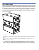
CHAPTER 8: MCF-1100 CASTER FRAME The optional MCF-1100 caster frame safely supports up to three 1100-LFCs for transport, making it easy to assemble and disassemble arrays in blocks of three cabinets. The caster frame’s sturdy construction allows it to be conveniently moved with forklifts. The MCF-1100 can also be used to support 1100-LFCs in groundstacked configurations. MCF-1100 Caster Frame 1100-LFC cabinets need not be equipped with the MRF-1100 rigging kit for transport with the caster frame.
CHAPTER 8: MCF-1100 CASTER FRAME 1100-LFC cabinets equipped with the MRF-1100 rigging kit provide for more secure transport as the bottom cabinet can be linked and pinned to the caster frame (see Figure 2). Each of the three cabinets can be linked and pinned together as well. Figure 2: MCF-1100 Caster Frame with 1100-LFC Stack with Rigging Kits (MTG-1100 Top Grid on Top) TIP: The MTG-1100 top grid can travel installed on top of 1100-LFC stacks.
MG-MINA GRID ASSEMBLY GUIDE MCF-1100 Caster Frame Dimensions 52.24 [1327 mm] 51.49 [1308 mm] Ø0.55 [Ø14 mm] 24.09 [612 mm] 10.62 [270 mm] 8.25 [210 mm] 44.70 [1135 mm] 25.50 [648 mm] 56.32 [1431 mm] 34.75 [883 mm] MCF-1100 Caster Frame Dimensions MCF-1100 Caster Frame Weight: 138 lbs (62.6 kg) 99" x 232" 90" x 232" LEO 45.00" x 29.75" 1100-LFC 56.32" x 34.75" LEO 45.00" x 29.75" 1100-LFC 56.32" x 34.75" MILO 58.625" x 23.50" MCF-1100 Truck Packing Examples 1100-LFC 56.32" x 34.
CHAPTER 8: MCF-1100 CASTER FRAME SAFETY GUIDELINES FOR THE MCF-1100 CASTER FRAME ■ Do not stack more than three 1100-LFCs on the caster frame. ■ Use straps when transporting 1100-LFCs that have not been fitted with the MRK-1100 rigging kit. ■ Avoid moving stacks in the front-to-back direction of the 1100-LFCs (the long side); always move stacks sideways to avoid tipping. ■ When lifting an 1100-LFC stack with a forklift, always keep the forks wide and close to the caster frame’s wheels.
APPENDIX A: ASSEMBLING ARRAYS WITH THE MTG-1100 TOP GRID To assemble an 1100-LFC array with the MTG-1100 top grid: 1. Attach the MTG-1100 top grid to the motors: ■ Place the MTG-1100 on the floor or on a road trunk in the approximate location where the rigging points have been established and the motors have been hung. ■ Attach 7/8-inch shackles to the desired attachment points on the MTG-1100 (see Chapter 5, “MTG-1100 Pickup Configurations”).
APPENDIX A: ASSEMBLING ARRAYS WITH THE MTG-1100 TOP GRID ■ Lower the suspended loudspeakers so the bottom cabinet is approximately 1 inch above the top cabinet on the floor. Adjust the placement of the stack on the floor so the top cabinet’s rigging bars align with those of the suspended cabinet above it. Extend the GuideALinks from the top cabinet into the slots of the suspended cabinet above it. Don’t worry if you can’t yet pin the GuideALinks to the suspended cabinet.
Meyer Sound Laboratories Inc. 2832 San Pablo Avenue Berkeley, CA 94702 www.meyersound.com T: +1 510 486.1166 F: +1 510 486.835 © 2012 Meyer Sound. All rights reserved. MTG-1100 Grid Assembly Guide — 05.220.030.