Operating Instructions SB-1 Parabolic Sound Beam Copyright 1998 Meyer Sound Laboratories, Inc. All rights reserved Part Number 05.049.048.
Contents AC Power .................................................. 3 Audio Input ................................................. 4 AC Troubleshooting ...................................... 5 Limiting and Protection Circuitry ..................... 5 Fans and Cooling Systems ............................. 7 Yoke Installation and Removal ........................ 6 Cover Removal and Installation ........................ 8 High Frequency Pod Installation and Removal ...... 8 Driver Phase Verification .......
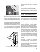
Product Summary The Meyer SB-1 Parabolic Sound Beam is the first device that propagates sound waves with SPLs that decrease as little as 3 dB per doubling of distance for more than 300 ft, across a five-octave frequency range, with a consistent and narrow beam width. The physical construction of the SB-1 consists of a fiberglass parabolic reflector dish with a bullet-shaped pod containing a 4” compression driver and an aspherical horn mounted over, and aimed at, the center of the dish.
Keep all liquids away from the SB-1 to avoid hazards from electrical shock. Do not operate the unit if the power cables are frayed or broken. The minimum electrical service amperage required by a system of SB-1s is the sum of the maximum continuous RMS current for each speaker. We recommend allowing an additional 30% above the minimum amperage to prevent peak voltage drops at the service entry. Safety Issues Pay close attention to these important electrical and safety issues.
AC Troubleshooting If the Active lamp does not light after connection to an AC source for three seconds, the problem is probably in the power supply. In the unlikely case that the circuit breakers trip (the white center buttons pop out), the amplifier or power supply may be malfunctioning. Do not reset the breakers! Contact Meyer Sound for repair information. If abnormal noise (hum, hiss, popping) is produced from the loudspeaker, disconnect the audio source from the speaker.
Fans and Cooling System The SB-1 uses a forced-air cooling system with two fans to prevent the amplifiers from overheating. A variable-speed primary fan runs continuously with an inaudible operating noise of 22 dBA at 1 m at its slowest speed. The speed of the primary fan begins increasing when the temperature of the heatsinks reaches 42°C. The fan reaches full speed at 62°C and is barely audible near the cabinet, even without an audio signal.
Lay the positioning yoke on the ground so that the hole closest to the front of the yoke is aligned with the 3/4” threaded rigging hole on both sides of the SB-1 The hanging method: On the top of the SB-1 is a single rigging point which can be used to hang the SB-1 for easy yoke installation and removal. . Connect the rigging hardware to the rigging plate.
Cover Removal and Installation The Dish cover is held in place by four sets of C-brackets and locking pins as shown below. Once each of the pins are removed, the cover can be easily lifted off the SB-1. To install the cover, reverse these steps. High Frequency Pod Installation and Removal. The High Frequency Pod is stored inside the SB-1 during transportation. To install the Pod onto the dish first loosen the 3/4” grade bolts on the yoke so that the dish is pointing upwards.
When you have verified the pod position, connect the EP-4 pin connectors. The SB-1 is now ready for operation. When removing the high frequency pod be careful not to let the weight of the pod bend any of the brackets as this will skew the position of the pod and damage the SB-1. When placing the pod back in the internal compartment remember to position the legs between the foam inserts.
Safety Summary English • To reduce the risk of electric shock, disconnect the loudspeaker from the AC mains before installing audio cable. Reconnect the power cord only after making all signal connections. • Connect the loudspeaker to a two-pole, three wire grounding mains receptacle. The receptacle must be connected to a fuse or circuit breaker. Connection to any other type of receptacle poses a shock hazard and may violate local electrical codes.
Controls and Connectors Rear User Panel shown with the optional Remote Monitoring System (RMS) panel European Rear User Panel with IEC 309 connector Physical Dimensions Front Packed for shipping (with yoke) Side 54.0 18.0 54.0 48.5 Weight: SB-1: 293 lb (133 kg); SB-1 with yoke: 392 lb (178 kg) Contact Information Meyer Sound Laboratories, Inc.