
Operating instructions


24
CHAPTER 5
The M3D-Sub has advantages over other subwoofers due
to its unique low-frequency directional control and its abil-
ity to be vertically arrayed with MILO/MILO 120 since they
share the same width.
NOTE: For most applications, you want to
keep low frequencies from being produced
behind the array to reduce or eliminate the low
frequency reverberant noise traditionally associ-
ated with large-scale, full range loudspeaker arrays.
The M3D-Sub’s award-winning and patent-pend-
ing cardioid directional pattern provides maximum
cancellation from 6 to 12 meters behind the cabinet
(-20 dB at 8 meters).
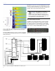
Table 5.1 shows how you can integrate MILO/MILO 120 with
M3D-Sub using the LD-3’s filtering capabilities to fine-tune
the system. All data in Table 5.1 is based on designs with a
2:1 ratio and in a close-proximity, coplanar orientation.
NOTE: When loudspeakers and subwoof-
ers are separated by more than 4 feet – or
delay must be used between them – a measurement
system such as the SIM audio analyzer (covered in
chapter 6) should be used to determine the correct
delay and polarity.
Table 5.1: MILO/MILO 120 and M3D-Sub
HPF LPF
ø Reverse
Switch
Result
80 80 Engaged Flat response
80 Off Engaged Flat response
160 Off Engaged Very flat response
Off Off Off Boost in the 80 Hz region
MILO/MILO 120 and the 700-HP Subwoofer
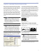
In applications where M3D-Sub features like directional low-
frequency control are not needed, a MILO/MILO 120 array
can be deployed in combination with Meyer Sound 700-HP
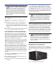
subwoofers (Figure 5.5). The 700-HP subwoofer extends the
MILO/MILO 120 system frequency response down to 30 Hz.
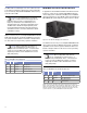
Figure 5.5. The 700-HP ultrahigh-power subwoofer
The Table 5.2 show how you can integrate MILO/MILO 120
with a subwoofer like the 700-HP using the LD-3’s filtering
capabilities to fine-tune the system. All data in Table 5.2 is
based on designs with a 2:1 ratio and in a close-proximity,
coplanar orientation.
NOTE: When loudspeakers and subwoof-
ers are separated by more than 4 feet – or
delay must be used between them – a measurement
system such as the SIM audio analyzer (covered in
chapter 6) should be used to determine the correct
delay and polarity.
Table 5.2: MILO/MILO 120 and 700-HP Subwoofer*
HPF LPF
ø Reverse
Switch
Result
Off Off Engaged Boost in the 100 Hz region
160 Off Engaged Very flat response
80 80 Off Very flat response
160 80 Off Flat response
*NOTE: Because the 700-HP and the 650-P subwoofers have identical
phase on their operating range, this table also applies when using the 650-P
subwoofer. However, due to the higher output and headroom of the 700-
HP, when using the 650-P a lower ratio must be used to achieve the same
system headroom, e.g., three MILO/MILO 120 with two 650-P.