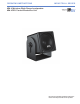
OPERATING INSTRUCTIONS INDUST RIA L SER IES MM-4 Miniature Wide-Range Loudspeaker MM-4CEU Control Electronics Unit Keep these important operating instructions. Check www.meyersound.com for updates.
Declaration of Conformity According to ISO/IEC Guide 22 and EN 45014 Manufacturer's Name: Meyer Sound Laboratories Inc. Manufacturer's Address: 2832 San Pablo Avenue Berkeley, California 94702-2204, USA declares that the product Product Name: MM-4CEU Product Options: All conforms to the following Product Specifications Safety: EN 60065: 2002 1 EMC: EN55103-1: 1997 emission 2 EN55103-2: 1997 immunity This device also complies with EN 55103-1 & -2.
Symbols Used These symbols indicate important safety or operating features in this booklet and on the chassis: Dangerous voltages: risk of electric shock Important operating instructions Frame or chassis Protective earth ground Pour indiquer les risques résultant de tensions dangereuses Pour indequer important instructions Masse, châssis Terre de protection Zu die gefahren von gefährliche spanning zeigen Zu wichtige betriebsanweisung und unterhaltsanweisung zeigen Rahmen oder chassis Die schutze
Safety Summary English - - - - - - To reduce the risk of electric shock, disconnect the loudspeaker from the AC mains before installing audio cable. Reconnect the power cord only after making all signal connections. Connect the loudspeaker to a two-pole, three-wire grounding mains receptacle. The receptacle must be connected to a fuse or circuit breaker. Connection to any other type of receptacle poses a shock hazard and may violate local electrical codes.
Contents Introduction The MM-4 Miniature Wide-Range Loudspeaker The MM-4CEU Control Electronics Unit (Required) 1 1 Chapter 1: Installing the MM-4 Loudspeaker 3 Using the MUB-MM4 U-Bracket Using the MFMA-MM4 Adapter Loudspeaker Connections Standard Connector Weather-Protected Connector Effect of Cable Resistance on System Performance 3 3 3 4 4 4 Chapter 2: The MM-4CEU Control Electronics Unit Frequency and Phase Response Correction Driver Protection AC Power Safety Issues Line Level Inputs Line Level
vi
INTRODUCTION INTRODUCTION As you read this manual, you’ll find figures and diagrams to help you understand and visualize what you’re reading. You’ll also find numerous icons that serve as cues to flag important information or warn you against improper or potentially harmful activities. These icons include: A NOTE identifies an important or useful piece of information relating to the topic under discussion. A Tip offers a helpful tip relevant to the topic at hand.
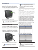
INTRODUCTION The MM-4CEU is specifically designed and required for use in an MM-4 loudspeaker system. In conjunction with professional grade amplifiers, the MM-4CEU protects your MM-4 loudspeakers against damaging overload conditions, while ensuring that they meet their published specifications.
CHAPTER 1 CHAPTER 1: Installing The MM-4 Loudspeaker The following MM-4 mounting options accoommodate a variety of different installation requirements: The MUB-MM4 U-bracket, which allows the MM-4 to be mounted on virtually any flat surface and enables you to change the angle of the MM-4 with respect to the mounting surface. The MFMA-MM4 flush mount adapter, which fits standard 8-inch loudspeaker bezels, for flush-mounting ceiling or in-wall applications.
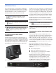
CHAPTER 1 Standard Connector TIP: The chassis-mount EN3 connectors on the MM-4 rear panel are fitted with captive plastic caps. If you are not using the second connector for looping, use the cap to seal it against moisture invasion. A Phoenix-style keyed connector is fitted to the indoor version of the MM-4 (Figure 1.3). The connector is wired with the left terminal as negative (-) and the right terminal as positive (+), when viewing the loudspeaker from the rear.
CHAPTER 2 CHAPTER 2: The MM-4CEU Control Electronics Unit The MM-4CEU is a required component for every MM-4 installation. It performs a number of important signalprocessing functions to ensure that the MM-4 meets its published specifications and is protected against damaging overload conditions. The MM-4CEU mounts in a standard 19-inch relay rack and occupies a single rack space (1.75 inches).
CHAPTER 2 AC Power Do not use a ground-lifting adapter or cut the AC cable ground pin. Keep all liquids away from the MM-4CEU to avoid hazards from electrical shock. Do not operate the unit if the power cables are frayed or broken. The MM-4CEU accommodates international power standards in two ranges: 90 to 130 V AC and 180 to 260 V AC, 50/60 Hz. A rear-panel switch selects between the two.
CHAPTER 2 NOTE: Most source equipment is safe for driving loads no smaller than 10 times the source’s output impedance. For source equipment with driving capability of 600 ohms, 16 MM-4CEUs could be safely driven in parallel (10 kOhms divided by 16 equals 625). CAUTION: Shorting any input connector pin to the chassis can create a ground loop and cause hum. ! TIP: If abnormal noise (hum, hiss, popping) is produced from the loudspeaker, disconnect the audio source from the MM-4CEU.
CHAPTER 2 NOTE: Amplifiers #1 and #2 are the amplifiers with the highest gain. Channel 2 SpeakerSense Channel 1 SpeakerSense Figure 2.2.
CHAPTER 3 CHAPTER 3: Choosing a Power Amplifier The MM-4 is designed for high-quality distributed sound systems. To realize the MM-4’s full capabilities, a directdrive power amplifier capable of 49 volts rms (70 volts peak) at the rated load impedance presented by the line configuration is required. The MM-4 presents a nominal load of 16 ohms, and each unit must be wired in parallel with the line. As shown in Table 3.
CHAPTER 3 Power Supply Some amplifiers are designed so that the internal power supply rails sag as the load current increases. While the amplifier’s rated continuous output at a given load may appear high, its peak output voltage varies with the load impedance. Because a loudspeaker’s impedance changes with frequency, such an amplifier will clip prematurely at low points in the loudspeaker’s impedance curve, and may deliver too high a voltage at high impedance points.
CHAPTER 4 CHAPTER 4: System design and Integration tools Meyer Sound offers two comprehensive tools to assist you with the acoustical and functional requirements of system design and optimization. This chapter introduces you to MAPP Online Pro, Meyer Sound’s powerful online acoustical prediction tool, and SIM 3, a robust instrumentation package for system measurement, analysis, and more.
CHAPTER 4 The key to MAPP Online Pro’s value is the accuracy of its predictions. Performance predictions for each Meyer Sound loudspeaker found in MAPP Online Pro are based on a model of that product built from 360 1/48th-octave–band measurements taken with a SIM audio analyzer in our anechoic chamber. The extreme consistency found from cabinet to cabinet in Meyer Sound products guarantees that the predictions MAPP Online Pro makes from this highresolution data will closely match actual performance.
APPENDIX A Appendix A MM-4 Weather Protected Cable Assembly Procedure Boot Coupling Ring Cord Connector Cable Cable Clamp Housing Contact Pins Step 1: Feed the end of the cable through the boot, cable clamp housing, and coupling ring in the order and position shown. Cord Connector Cable Dot (pin 1 3/8" Max. Solder indicator) 2+ 1- 17/32" 2+ 9/32" Contact Pins Step 2: Strip cable as shown and solder conductors to pins.
APPENDIX B Appendix B MM-4 Specifications Acoustical (MM-4CEU required) Note: To realize the MM-4’s full capabilities, an MM-4CEU must be used. The amplifier driving the loudspeakers should be capable of 49 volts RMS at the rated load impedance, and provide a voltage gain between 10 and 30 dB (20 dB for optimal S/N ratio and protection).
APPENDIX C Appendix C MM-4CEU Specifications Audio Input Type Differential, electronically balanced; RF and transient protected Max common mode range ±15 V DC, clamped to earth for voltage transient protection Connector(s) Two female XLR, one for each input channel Input Impedance 10 kΩ differential between pins 2 and 3 Wiring Pin 1: Chassis/earth through 11 kΩ, 1000 pF, 15 V clamp network to provide virtual ground lift at audio frequencies; Pin 2: Signal +; Pin 3: Signal -; Case: Earth ground and
APPENDIX D Appendix D MM-4 EN3 Fire Alarm Signaling Specifications Acoustical (Fire Alarm Amplifier Required) Frequency response Fire alarm; 400 Hz to 4 kHz Note: Stated per the UL 1480 reporting method. Maximum continouos SPL UL1480 sound pressure level 89 dB at 10 FT 10 kΩ differential between pins 2 and 3 Note: Measured per UL1480. ULC S541 sound pressure level 104 dB at 3m Note: Measured per ULC S541. ! Caution: Do not use the Fire Signaling MM-4 in air handling spaces.
Meyer Sound Laboratories Inc. 2832 San Pablo Avenue Berkeley, CA 94702 www.meyersound.com T: +1 510 486.1166 F: +1 510 486.8356 © 2010 Meyer Sound Laboratories Inc. 05.091.012.01 Rev.