MTS-4A Self-Powered Loudspeaker Systems OPERATING INSTRUCTIONS OPERATING INSTRUCTIONS Superior engineering for the art and science of sound. Keep these important operating instructions Check www.meyersound.
CONTENTS Safety Summary The MTS-4A: Introduction AC Power Audio Input Amplification and Protection Circuitry Rigging Measurement and System Integration Tools Complete Systems Driver Troubleshooting Array Design MTS-4A Specifications MTS-4A Dimensions Contact Information 3 4 4 6 6 7 8 8 9 10 12 13 14 SYMBOLS USED SYMBOLS INDICATE IMPORTANT SAFETY OR OPERATING FEATURES IN THIS BOOKLET AND ON THE CHASSIS.
! ENGLISH • To reduce the risk of electric shock, disconnect the unit from the AC mains before installing audio cable. Reconnect the power cord only after making all signal connections. • Connect the unit to a two-pole, three wire grounding mains receptacle. The receptacle must be connected to a fuse or circuit breaker. Connection to any other type of receptacle poses a shock hazard and may violate local electrical codes. • Do not allow water or any foreign object to get inside the unit.
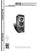
THE MTS-4A: INTRODUCTION The Meyer MTS-4A self-powered loudspeaker is a compact, self-contained, full-range system suited for clubs and small theatres (throw distances less than 100 ft). Its trapezoidal shape facilitates array design that maximizes coverage and SPL for the size of the array. Since all frequencies are produced from one cabinet, the MTS-4A better approximates a pointsource radiator, creating a smoother frequency image than separate mid-hi and subwoofer cabinets.
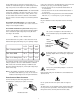
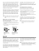
If the colors referred to in the diagram don't correspond to the terminals in your plug, use the following guidelines: • Connect the blue wire to the terminal marked with an N or colored black. • Connect the brown wire to the terminal marked with an L or colored red. • Connect the green and yellow wire to the terminal marked with an E (or ) or colored green (or green and yellow).
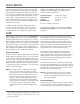
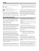
AUDIO INPUT with XLR connectors for balanced signal sources. The MTS-4A presents a 10 kΩ balanced input impedance to a three-pin XLR connector wired with the following convention: Pin 1 Pin 2 Pin 3 Case NOTE: If abnormal noise (hum, hiss, popping) is produced from the loudspeaker, disconnect the audio source from the speaker. If the noise stops, then the problem is not within the loudspeaker; check the audio input and AC power.
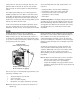
at close proximity without an audio signal and turn on in response to compressed air to clear dust from the grill, filter, fans, and heatsinks. Make sure that the air ducts are clear and that there is at least six inches clearance for exhaust behind the cabinet. • primary fan failure (check its status immediately); • accumulation of dust in the cooling system path; • a prolonged period of high source levels in hot temperatures or direct sunlight; • driver failure.
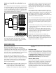
MEASUREMENT AND SYSTEM INTEGRATION TOOLS It is essential that even the most carefully assembled sound systems be analyzed with precise measurement tools. We recommend using the Meyer Sound SIM® System II Sound Analyzer1 and CP-10 Parametric Equalizer2 to dB/oct, Q = 0.8) that performs a crossover function for the Mid-Hi output. • The DS-2 & Sub Crossover switch (channels 1 and 2 only) activates a crossover network optimized for the DS-2P or DS-4P when used with the 650-P.
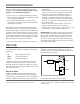
LD-1A FLOOR WITH FLOWN MTS-4A AND CQ; 650-P The CH 1 Mid-Hi and CH 3 outputs drive the upper and lower MTS-4A arrays, respectively, applying appropriate levels for speakers directed at different distances. CH 3 is delayed to phase align the upper and lower systems in the intersecting coverage area. ON THE This example shows the LD-1A integrating a complete system of self-powered speakers for a large venue.
The polarity is correct if the frequency response is smooth through each crossover region (40 Hz, 100 Hz, 1 kHz). Cancellation greater than 6 dB in any region indicates polarity reversal between the drivers on either side of that crossover point. We do not recommend using phase poppers to analyze driver polarity. The phase response for all drivers varies, to some degree, over the frequency range in which it operates.
ARRAY DESIGN FOR (without a nearby wall or ceiling) do not. In general, subwoofers in half-space generate twice the SPL (+6 dB) compared to the same number in free-space. LOW FREQUENCIES Since the MTS-4A contains sub and low frequency drivers, in addition to mid and high drivers, array design for the MTS-4A must incorporate the different array response of high and low frequencies. The beam width for a single speaker widens as the frequency decreases.
MTS-4A SPECIFICATIONS Acoustical1 (each loudspeaker) Operating Frequency Range2 Free Field Half-Space Phase Response Maximum Peak SPL3 Signal to Noise Ratio Coverage -6 dB at 70° H x 60° V Sub Low Mid High Transducers Audio Input 26 Hz - 18 kHz ± 6 dB 32 Hz - 16 kHz ± 4 dB 30 Hz - 16 kHz ± 4dB ± 70° 90 Hz - 17.
MTS-4A DIMENSIONS All units in inches 10.63 13.00 21.97 21.26 13.16 13.36 30.26 Bottom Top 7.5 30.00 14.125 56.75 28.
CONTACT INFORMATION Meyer Sound Laboratories, Inc. 2832 San Pablo Avenue Berkeley, CA 94702 tel: 510.486.1166 fax: 510.486.8356 e-mail: info@meyersound.com www.meyersound.com 05.029.006.02 Rev A Check www.meyersound.