USER GUIDE RMS 4.
© 2004 Meyer Sound. All rights reserved. RMS™ 4.5 Remote Monitoring System User Guide The contents of this manual are furnished for informational purposes only, are subject to change without notice, and should not be construed as a commitment by Meyer Sound Laboratories Inc. Meyer Sound assumes no responsibility or liability for any errors or inaccuracies that may appear in this manual.
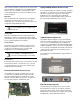
CONTENTS INTRODUCTION 1 How to Use this Guide Introducing the RMS™ Remote Monitoring System User Interface Network Hardware How this Guide Is Organized 1 1 1 1 2 CHAPTER 1: Planning and Designing for RMS 3 System Requirements Hardware Components The RMS User Panel Network Connectors Service LED (Red) Wink LED Activity LED Service Button Reset Button Desktop PCI Network Interface Card Laptop PCMCIA Network Interface Card i.
CHAPTER 3: Installing Software and Network Adapters Backing Up and Importing the RMS Database Backing Up your RMS Database and Panel Files Removing and Importing a Network Database Removing a Network Database Importing a Network Database Installation and Setup Launching RMS Setup Validating the Network Interface Card (Not necessary for i.LON only users) Running RMS for the First Time Connecting and Configuring the i.LON 10 Ethernet Adapter Connecting the i.LON 10 Configuring the i.
INTRODUCTION INTRODUCTION HOW TO USE THIS GUIDE As you read this guide, you’ll find figures and diagrams to help you understand and visualize what you’re reading. You’ll also find numerous icons that flag important information or warn you against improper or potentially harmful activities.
INTRODUCTION HOW THIS GUIDE IS ORGANIZED The RMS 4.5 User Guide is divided into four chapters plus an appendix that contains useful keyboard shortcuts for the RMS application. An RMS configuration data sheet, for logging information about the loudspeakers on your RMS network, is also included at the end of the guide. The chapters are organized as follows: ■ Chapter 1, “Planning and Designing for RMS,” gets you started by showing you how to plan your RMS network.
CHAPTER 1 CHAPTER 1: PLANNING AND DESIGNING FOR RMS This chapter will help you understand the issues involved in planning an RMS network for your system design. Type of hardware, number of loudspeakers and their layout are all crucial to setting up a fast, trouble-free RMS network. SYSTEM REQUIREMENTS To ensure that the RMS monitoring system runs smoothly, the following system specifications are required: ■ Windows® 98SE/NT 4.0 (SP5)/2000/XP™ (SP1) or higher ■ Pentium® III processor or higher (350 MHz min.
CHAPTER 1 flash continuously. When continuously lit, the Service LED indicates that the loudspeaker has a local RMS hardware failure. In this case, the RMS communications module may be damaged and you should contact Meyer Sound Technical Support. Wink LED When the Wink LED is lit, it indicates that an identifying signal has been sent from the host computer to the loudspeaker. This is achieved using the service pin on the loudspeaker and the RMS application.
CHAPTER 1 NOTE: A repeater is a network device that connects multiple segments of a network cable. It re-times, strengthens, and regenerates the incoming signal then sends the signal back to the network. TWISTED PAIR VS. ETHERNET RMS is available in both twisted-pair and Ethernet versions.
CHAPTER 1 Twisted pair Figures 1.2 and 1.3 show typical network configurations for simple twisted-pair and twisted-pair repeater configurations. When designing a twisted-pair RMS network, pay close attention to the wiring, cable gauge, and connector requirements (discussed in the section “Network Specifications” later in this chapter) which are important to good performance.
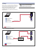
CHAPTER 1 Ethernet NOTE: An Ethernet-based RMS system is more complex from a design standpoint and must conform to Ethernet network design specifications (beyond the scope of this guide). A general knowledge of Ethernet networks is very helpful if you plan to deploy an Ethernet-based system. Figures 1.4 through 1.6 on the following pages show various network configurations for a simple Ethernet-based network configuration. Twisted Pair Network Cable Network Crossover Cable Laptop Loudspeakers (1-50) i.
CHAPTER 1 Ethernet Cat 5 Patch Cable RMS Work Station Twisted Pair Network Cable i.Lon 10 Static IP Address Loudspeakers (1-50) Twisted Pair Network Cable i.Lon 10 Static IP Address Loudspeakers (1-50) Intranet Ethernet Cat 5 Patch Cable Twisted Pair Network Cable Figure 1.6.
CHAPTER 1 Understanding the i.LON 10 As discussed earlier in this chapter, the i.LON 10 Ethernet Adapter converts twisted-pair network data to Ethernet network data, allowing you to connect RMS to one or more LNS servers via the TCP/IP protocol. Each i.LON 10 must have its own static IP address, which will provide its RMS identity as a network segment in the network database.
CHAPTER 1 NETWORK SPECIFICATIONS Maximum Loudspeaker Nodes Connector Type ■ Twisted-pair system with a maximum of 62 nodes (maximum of 50 recommended); up to 115 nodes with a network repeater ■ 2-wire plug with recommended snap-on lock ■ Ethernet network with i.LON 10 with up to 50 nodes per network segment Twisted-Pair Cable Type ■ 20 AWG (Belden 8205 or equivalent) twisted pair, stranded, unshielded Ethernet Cable Type ■ Category 5 or higher. Straight-through (patch) cable if using a hub or a switch.
CHAPTER 1 RMS NETWORK DESIGN EXAMPLES Small- to Mid-Sized Venue This section focuses on examples of several RMS system designs that can serve as building block diagrams for an RMS network. These examples show how the twisted-pair and Ethernet connections are made to reduce network load. If you’re planning for a small- to mid-sized venue, a twisted-pair network is typical.
CHAPTER 1 Touring or Portable Applications Touring or portable applications may require a flexible twisted-pair network. Using a laptop and keeping your existing inventory of loudspeakers commissioned and organized will make using RMS simple to setup and easy to use.
CHAPTER 1 Large Venue Applications For larger venues such as theatres, stadiums, arenas, hotels, and theme parks, an Ethernet-based network, using multiple i.LON 10s, is preferred for increased network speed and durability. When planning an Ethernet network you still have to convert to twisted pair from the i.LON 10 to your loudspeaker locations. Doing so allows you to form a hybrid network between twisted-pair and Ethernet type cabling (10BASE-T).
CHAPTER 1 Design Tips for RMS networks Different designs have their own strengths and weaknesses. The following tips will help you make the most out of your RMS network design: ■ Avoid making “dedicated single runs” for each loudspeaker in a system design. Make only a single twisted-pair run to loudspeaker locations or arrays when possible. Once you have reached the loudspeaker location and array, daisy-chain or loop through all the loudspeakers in the array.
CHAPTER 2 CHAPTER 2: INSTALLING TRANSITION HARDWARE This chapter will cover installation and configuration of many of the hardware devices you may encounter during an RMS installation. NOTE: RMS-equipped loudspeakers ship by default with a spare jumper to enable/ disable the loudspeaker’s Mute functionality, unless you request the jumper to be pre-installed when the order is placed.
CHAPTER 2 4. While slowly removing the amplifier's user panel, disconnect the signal cable from the input board on the user panel by disengaging the gray connector and disconnect the AC input connector (4-wire green connector) from the AC mains board. 5. Remove the blank plate from the user panel by removing the two nuts on the back of the user panel. 6. Looking in to the power supply chassis, locate the back right screw hole (next to the transformer) on the floor of the power supply chassis.
CHAPTER 2 8. Remove the plastic connector (next to the fan power connector) on the power supply board. 10. Position the RMS communications module within the bottom of the power supply chassis so that the standoffs on the module align with the four screw holes in the bottom of the chassis and the LEDs are facing out. plastic connector 9. Apply one drop of Loctite® to each of the four standoffs on the RMS communications module. 11.
CHAPTER 2 12. While holding the RMS communications module in place, lay the unit on its side and secure the RMS communications module using the four screws provided with the kit. TIP: Insufficient grounding could be the result of over-thinning the back right screw hole (see Step 7). If this is the case, using a shorter screw may fix the problem. screws for assembling the RMS PCB assembly R13 13. Connect the 26-pin connector from the long ribbon cable to the RMS communications module connector.
CHAPTER 2 16. Replace the user panel with the eight screws to secure it to the chassis, making sure to carefully set the LEDs and the network connectors. INSTALLING OR UPGRADING AN RMS NETWORK COMMUNICATION MODULE (ULTRASERIES) 17. Affix the Neuron ID label to the bottom center of the User Panel. The modular amplifier and electronics in the self-powered UltraSeries are designed for maximum serviceability.
CHAPTER 2 2. Remove the four Phillips-head screws from the blank perforated plate or RMS communications module if installed and being replaced. Save the plate in case you need it in the future. screws 3. Make sure the copper strip on the left-hand side of the opening is properly positioned and not damaged. This strip contributes to the grounding of the RMS communications module to the chassis. If you need to replace the strip, please contact Meyer Sound. copper strip 4.
CHAPTER 2 MUTE-ENABLE JUMPER INSTALLATION Terminator InstallationCAUTION: (Terminators shipped with RMS Host Station Peripheral Kit) Be careful not to install the In order to use the Mute and Solo functions of any RMS-equipped Meyer Sound loudspeaker, a special jumper must be installed in the loudspeaker’s RMS communication module (the jumper ships as a separate item with the loudspeaker). To install the Mute-Enable jumper: 1.
CHAPTER 2 INSTALLATION AND OPERATION OF THE FTR120 NETWORK REPEATER The FTR-120 (Figure 2.6) is a four-channel network repeater. A message generated on any network segment to which the FTR-120 is connected is rebroadcast on the three other channels. Network Terminations The FTR-120 is capable of providing the standard network termination if desired. As shipped, each channel on the FTR-120 has 5-ohm network termination resistors connected.
CHAPTER 2 Wiring Universal Power Supply The FTR-120 is wired using five position terminal blocks. The wiring pin-out for the FTR-120 module is shown in Table 2.2. The universal power supply included in the repeater kit allows for FTR-120 operation around the world. The supply accepts any input voltage from 100 to 240 V AC, and produces the required 12 V DC output. The male IEC input allows for any mains lead adapter to be used with the supply. Table 2.
CHAPTER 2 24
CHAPTER 3 CHAPTER 3: INSTALLING SOFTWARE AND NETWORK ADAPTERS At the heart of the RMS remote monitoring system is a robust suite of software including the Echelon Drivers, Echelon LNS Server, and the RMS application. This chapter will show you how to install and set up these components. BACKING UP AND IMPORTING THE RMS DATABASE If you are upgrading to RMS version 4.
CHAPTER 3 Removing and Importing a Network Database You can remove an existing RMS database as well as import saved databases or databases you want to copy between different computers. 5. The database is no longer recognized in the RMS Network Manager, however it still exists in datestamped form in the C:\meyer\rms folder on your hard drive. Removing a Network Database Perform the following steps to remove an RMS database: 1. Launch RMS and open the RMS Network Manager. 2.
CHAPTER 3 Importing a Network Database If you have upgraded to a new version of RMS, if you have moved your database files to a new RMS host computer, you will need to import your RMS database. 7. You will be prompted with two warnings. Click OK and Yes, respectively, to dismiss both warning dialogs. Perform the following steps to import an RMS database: 1. If RMS is running, shut it down. 2. Locate your backed-up RMSNET folder. Copy it into the C:\meyer\rms folder. 3.
CHAPTER 3 INSTALLATION AND SETUP As discussed in Chapter 1, do not install your network interface card (PCI or PCMCIA card) until after you have completed installation of all RMS software components. You will be prompted to select either a full or custom installation. Once the software is installed, you will need to shut down your computer and install the Network Interface Card.
CHAPTER 3 The last dialog of the wizard will prompt you to shutdown your computer. Select No, I will restart my computer later. 1. Inspect the NI Application drop-down box. If your Network Interface Card is a PCI card, make sure that NSIPCLTA is selected. If your card is a PCMCIA, NSIPCC should be selected. Manually shutdown your computer from the Start menu and install the Network Interface Card. When the Network Interface Card is installed, restart your computer, then launch RMS. Launch RMS. 2.
CHAPTER 3 Figure 3.1. Typical Diagnostics output 3. The LNS Server dialog appears. Click Exit, Close All. Figure 3.2. Diagnostics information after clicking the Test button If validation is unsuccessful, verify that the RMS software and hardware are working properly by taking the following steps: 1. From the Start Menu, Click Echelon LNS Utilities, LNS Server. 4. Start RMS. 2. The Network Interface dialog appears. Click OK. NOTE: The Network Interface dialog may take up to one minute to appear.
CHAPTER 3 RUNNING RMS FOR THE FIRST TIME After installing the RMS software, restarting your computer, and validating your Network Interface Card, RMS is almost ready to run! Double-click the RMS Icon on your desktop – or select RMS from the shortcut in the Meyer Sound folder in the Start menu – to launch the RMS software. NOTE: If you chose to add an RMS icon to your Startup folder during RMS software installation, RMS will automatically run when Windows starts.
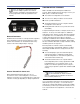
CHAPTER 3 CONNECTING AND CONFIGURING THE I.LON 10 ETHERNET ADAPTER By following the steps outlined in this section, you can quickly and easily configure your i.LON Ethernet Adapter to communicate with your computer. Figure 3.6 shows the i.LON 10 Ethernet Adapter (FT Model) from the top and from the back, showing all hardware inputs and outputs. NOTE: See Chapter 1, “Planning and Designing for RMS,” for additional examples and diagrams for how to setup your i.LON 10 based network.
CHAPTER 3 NOTE: If you are using Windows 98, you may need to restart after making the changes in step 3. 4. Open your Web browser and enter in the following address to gain access to the i.LON 10: http://192.168.1.222/config 5. You will be prompted for a user name and password. Enter the following: User Name: ilon Password: ilon 2. On the General tab, highlight Internet Protocol (TCP/IP) and select Properties. The Properties dialog appears. 3. Click the Use the following IP address radio button.
CHAPTER 3 NOTE: You must check both checkboxes to be allowed access to the i.LON 10 only after you have completed its configuration. 9. Click the Setup link on the left side navigation menu. The Setup page appears. 10. In the Hostname field, enter the name of the i.LON 10 that you wish to communicate with the network. The name must begin with ilon, followed by a dash -, followed by a number in sequence. For example, the first i.
CHAPTER 3 Configuring the LonWorks Interface The LonWorks Interfaces program on your computer keeps track of the i.LON 10 adapters you specify. The interface manages the connection between your computer and the i.LON 10(s) on your RMS network. 3. Click the Address/Port tab, then check the Use Static IP Address radio button. Enter the exact IP address you used in the i.LON 10 that you configured in the last section (for example, ilon-1 and 192.168.1.101).
CHAPTER 3 Initializing the i.LON 10 into the RMS Database 1. Launch RMS and open the Network Server and Manager, then open the Network Manager. Click Add. 5. Click Yes to dismiss the warning dialog. The Network Server and Manager will shut down and reopen, initializing the database and the i.LON 10. 6. When the Network Server and Manager reopens, you will see the new i.LON 10 initialized on the network. 2. In the Network Types section, click the Remote network (RMSNETx) accessed with an i.
CHAPTER 4 CHAPTER 4: USING RMS SOFTWARE This chapter will walk you through the capabilities and functionality of the RMS application. USING THE RMS APPLICATION The RMS application is dual-purpose. First, you add virtual loudspeakers to a Page which represents the layout of your loudspeaker configuration. Second, you monitor the real, functioning loudspeakers through different graphical views available to you on each Page.
CHAPTER 4 3. Click OK to add the new Page. The new Page appears as a new tab to the right of the last Page created and becomes the current Page. Adding and Commissioning a Loudspeaker ■ Press Tab to cycle through the Pages from left to right. Once you’ve created a Page, the next step is to add the loudspeakers you want to monitor. Once added, you commission the loudspeaker to establish a link between it and the RMS application.
CHAPTER 4 To add and commission a loudspeaker, perform the following steps: 4. Click OK. The Commission the Loudspeaker on the Network dialog appears. 1. From the Add menu, click the name of the loudspeaker you want to add. The Add Loudspeaker dialog appears. 5. In the Device Type drop-down box, select either RMS3 or Prod6h according to the type of firmware the loudspeaker supports. Click Commission to connect to the loudspeaker on the network. 2.
CHAPTER 4 7. RMS now displays an icon representing the loudspeaker you added on the current Page. If the loudspeaker is online, the Speaker Communications Indicators will be green. Understanding Device Credits During the commissioning process, a loudspeaker sends a unique Neuron ID which, in conjunction with the Device Name you give it, uniquely identifies that loudspeaker on the network. If commissioning is successful, you are “credited” with a loudspeaker being present on the network.
CHAPTER 4 Commissioning Loudspeakers Using the Neuron ID Number RMS-equipped Meyer Sound loudspeakers manufactured in July 2003 and later display a label on the user panel with the unique Neuron ID number of the RMS module. This number can be used to commission the loudspeaker without pressing the Service Pin. To commission a loudspeaker using the Neuron ID number, perform the following steps: 1. Ensure that the loudspeaker is powered on and connected to the host computer. 2.
CHAPTER 4 Managing Devices Previously commissioned loudspeakers from one Panel are available to other Panels using the same network database; a physical loudspeaker can be added to another Panel with the same Device Name without being recommissioned or using an additional Device Credit. In addition, Loudspeakers that have already been added and commissioned in the Panel you’re working in can be copied to new Pages.
CHAPTER 4 Deleting a Loudspeaker To delete a loudspeaker, perform the following steps: 1. Right-click on the loudspeaker icon in Speaker View (anywhere except the title bar) and click Delete. CAUTION: Deleting a loudspeaker from any Page deletes the loudspeaker from all Pages – not just the Page the loudspeaker is on. 2. A dialog appears, asking you to confirm the deletion. Click OK to delete the loudspeaker. The Remove Loudspeaker From Network dialog appears.
CHAPTER 4 Table 4.1 Monitor Parameters in Icon View for the MILO Loudspeaker Parameter Function Title Bar Displays the Speaker Title and/or Device Name Loudspeaker Communication Green: Loudspeaker online Red: Information is not being received from the loudspeaker (offline) Using Figure 4.8 as a guideline, Table 4.2 explains all of the monitoring capabilities available in Meter View for the MILO loudspeaker. Table 4.
CHAPTER 4 Text View Text View (Figure 4.9) is the most complete monitoring view in RMS, with a host of important data displayed using text fields. Table 4.
CHAPTER 4 Working with Views The Properties Menu You can show or hide views for any loudspeaker in a number of different ways by doing any of the following: In addition to showing and hiding Loudspeaker Views, the Properties menu (Figure 4.10) performs the following functions: ■ Right-click anywhere except on the Title Bar on any visible view to display the Properties menu. A check mark beside a view indicates it is already open.
CHAPTER 4 Control Functions Wink You can use RMS to control Mute, Solo and Wink functions. Mute and Solo are essential to RMS troubleshooting techniques, while Wink identifies the physical loudspeaker to the Loudspeaker View in a Panel. The Wink function allows you to identify the physical loudspeaker corresponding to a Loudspeaker View. To wink a loudspeaker, perform the following steps: Mute Simply click the Mute button on any Loudspeaker View to mute that loudspeaker.
CHAPTER 4 You can freely add loudspeakers anywhere in the matrix and name each column according to your system configuration. To set up the Solo/Mute Matrix, do the following: 1. From the Muting menu bar, you click on Solo/Mute Matrix. The Solo/Mute Matrix dialog appears. 2. Right-click on a column head and choose Name Column. The Name Control Column appears. 5. Select one or more loudspeakers and click Add. If you selected one loudspeaker, it appears in the selected cell.
CHAPTER 4 RMS saves your matrix configuration automatically to a file, and the last saved setup will reload when you call up the Solo/Mute Matrix dialog. You can also work with your own matrix files from the Solo/Mute Matrix dialog by using its menu bar: Operations in the Solo/Mute Matrix Controller affect selected loudspeakers only (with the exception of global operations like Mute All). To select loudspeakers: ■ Click on a cell to select a single loudspeaker.
CHAPTER 4 The Options Menu Title Status Bar Choose Options, Title from the Menu Bar to open the Set Title Type dialog. This dialog determines whether the device name or speaker title appears in the title bar of the speaker view. The Status Bar shows the polarity convention used for the current panel, whether muting is enabled/disabled, and how many loudspeakers of the total in the panel are online. The Status Bar will show 2+/3+ if both polarity settings are detected.
APPENDIX A APPENDIX A: RMS APPLICATION COMMAND KEY REFERENCE Key Command Ctrl+N New Panel Ctrl+O Open Panel Ctrl+S Save Panel Ctrl+A Add Page Ctrl+D Delete Page Ctrl+R Rename Page Ctrl+M Muting Options Ctrl+B Background Ctrl+C Network Setup Ctrl+T Title F12 Mute All F9 Unmute All F8 Solo/Mute Matrix Controller Tab Scrolls through Pages left to right Shift+Tab Scrolls through Pages right to left 51
APPENDIX A 52
APPENDIX B APPENDIX B: ADVANCED ILON 10 CONFIGURATION CONFIGURING I.LON IP INFORMATION CONFIGURING LNS SERVER IP INFORMATION Hostname The TCP/IP host name of the i.LON 10 Ethernet Adapter. Once your i.LON 10 Ethernet Adapter is established as part of a TCP/IP network, you can configure it to be able to communicate uplink with one or more LNS Servers. Set the following fields in the Setup Web page to allow the i.LON 10 to call uplink to an LNS Server: When the i.
APPENDIX B Save and Exit Click to close this page, write the configuration changes to FLASH memory, and reset the i.LON 10 Ethernet Adapter. Configuration changes will take effect upon reboot. After reboot, the Security page and the MD5 Authentication key will no longer be available until a security access reset is executed. Exit Without Save Click to close this page without saving changes. Any changes made will be lost. The i.
APPENDIX B This page contains the following options: Allow HTTP Access Set this option to allow users to access the i.LON 10 Web pages with the exception of the Firmware Page and the Security Page (both of which can only be accessed after a security access reset). If set, enter a Username and Password that will grant access. The Username and Password may contain up to 16 alphanumeric characters; they are case sensitive. By default, the Username and Password are set to ilon.
APPENDIX B 56
RMS CONFIGURATION DATA SHEET Customer Name Model Venue Loudspeaker Serial Number Neuron ID Device Name Date Notes
Meyer Sound Laboratories Inc. 2832 San Pablo Avenue Berkeley, CA 94702 www.meyersound.com T: +1 510 486.1166 F: +1 510 486.8356 © 2004 Meyer Sound Laboratories Inc. 05.033.302.