
User guide


iii
CONTENTS
INTRODUCTION 1
How to Use this Guide 1
Introducing the RMS™ Remote Monitoring System 1
User Interface 1
Network Hardware 1
How this Guide Is Organized 2
CHAPTER 1: Planning and Designing for RMS 3
System Requirements 3
Hardware Components 3
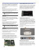
The RMS User Panel 3
Network Connectors 3
Service LED (Red) 3
Wink LED 4
Activity LED 4
Service Button 4
Reset Button 4
Desktop PCI Network Interface Card 4
Laptop PCMCIA Network Interface Card 4
i.LON 10 Ethernet Adapter I/O 4
FTR-120 Network Repeater 4
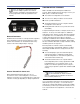
Network Terminator 5
Custom Twisted-Pair Connectors 5
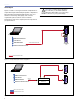
Twisted pair vs. Ethernet 5
Twisted pair 6
Ethernet 7
Understanding the i.LON 10 9
Hubs and Switches 9
Network Specifications 10
Maximum Loudspeaker Nodes 10
Twisted-Pair Cable Type 10
Ethernet Cable Type 10
Connector Types 10
Maximum Network length 10
Termination 10
Connector Type 10
Network Platform 10
Transceiver 10
Data Rate 10
RMS Network Design Examples 11
CHAPTER 2: Installing Transition Hardware 15
Installing an RMS Network Communication Module (MP or HP Amplifier) 15
Installing or Upgrading an RMS Network Communication Module (UltraSeries) 19
Copper Strip 20
Locking Connector 20
Mute-Enable Jumper Installation 21
Installation of the RMS Connector Assembly 21
Termination Installation 21
Installation and Operation of the FTR-120 Network Repeater 22
Mechanical Installation 22
Network Terminations 22
Wiring 23
Universal Power Supply 23
FTR-120 Specifications 23