
Service manual

Self-Powered Concert Series
Service Manual
MP-2/4 Amplifier
Doc #: 05.033.040.01
Rev.: A
Date: 08/31/98
Page: 9 of 26
© 1998 Meyer Sound Laboratories, Inc. All rights reserved.
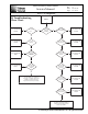
D) Block Diagram Description:
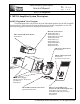
1) (Rear) User Panel:
The user panel block is divided into two main sections: AC Power and Audio Signal Path.
The AC power is applied to the system via a L6-20 twist-lock connector or an IEC 309 connector.
The line voltage is fed thru an RF filter and then connected to circuit breakers. For 115 V
applications, both circuit breakers are used. For 230 V applications, only one circuit breaker is
employed in the path of current. Note also that MP-2 amplifiers use 6 Amp breakers while MP-
4 amplifiers use 8 Amp breakers.
The audio signal is introduced to the system via a 3-pin XLR jack. The signal is fed to a
polarity switch and then to an RF filter. The audio pair (pins 2 and 3) is transmitted on a 10-
pin ribbon cable to the control board. In addition, feedback lines returning from the control
board on the ribbon cable power the LED's. Pin 1 is connected using a Ground Loop Isolation
Network to Chassis Ground. All the audio circuitry in the user panel is on the Audio Input
board.
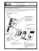
2) AC Mains Board:
The AC mains board is the heart of the Intelligent AC
®
system. This module is responsible
for the auto selection of line voltages. During a normal power-up procedure, the following
sequence of operations occur on the AC Mains module:
The AC input line from the user panel is fed to the "housekeeping supply" circuit (via a 125
mA fuse) and to the voltage auto-select circuit. The "housekeeping supply" generates 12 V DC
continuously (provided the AC line is within 80-270 V), which is used for powering compo-
nents that monitor line conditions and properly select winding taps for the main high power
supply. The voltage auto-select circuit utilizes a peak voltage detector and voltage comparators
to determine the line voltage and select the correct tap of the toroidal transformer.
After tap selection, the thermistor limits the inrush current and allows the unit to power-up.
After 2-3 seconds, a "turn-on delay" circuit (located on the power supply board-see sheet 2)
sends an "unmute" signal via the sense cable to the AC mains module and to the TPL Control
board. This "unmute" signal triggers Relay 1 on the AC mains module to shunt the thermistor
out of the circuit and to trigger the "unmute" relays on the TPL Control board (see sheet 1).
A "fault shutdown latch" is also located on the AC mains module. If this latch receives a fault
signal (from the Amplifier/Heatsink module), it will trigger the shut down of the unit. This
circuit stays latched until the AC power is completely removed and the "housekeeping supply"
drops to 0 V DC.
3) RMS (Remote Monitoring System) Communications Board:
This option allows you to monitor remotely certain parameters of the amplifier while in use.
As this module is quite complex, no system block will be given at this time. However, a brief
explanation of the connections follows: