
Service manual
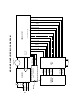


Caution: Be careful not to overflex the circuit board when removing the power
harness connector. The connector fits very snug; rock the connector length-wise
to work loose.
7. Lift the amp heatsink module out of the chassis and set aside. Do not remove
the control board from the amp heatsink assembly at this time.
Caution: Never disassemble the amplifier PCB board from the heatsink.
The torque on the FET’s is an exact measurement and should not be tampered
with. It will void any potential warranty.
If the top or the bottom amp heatsink module needs to be replaced refer to Meyer
Sound Self Powered Series MP-2 mp heatsink Service Procedure (#
17.033.013.01) for replacement procedures that apply to both the MP-2 and HP-
2 amplifiers or, contact the Meyer Sound Service Department for links to service
videos for this product.
8. With the amp heatsink removed, reset the breakers, and apply AC power to
the unit.
Check for the following conditions:
a) Audible power-up sequence (three clicks).
Note: This applies to AC supplies ranging from 110-130 V and 225-250 V.
For AC supplies between 90-105 V and 180-215 V, only two clicks will be
heard.
b) Center fan turns on.
c) Power supply LED’s are on (visible through the top of the chassis)
Note: The user panel LED will not light as the amp heatsink module is
disconnected.
9. If the previous three conditions in step 8 are met, the power supply circuits are
functioning properly. It is likely that the amp heatsink module is damaged and
will need to be replaced.
Refer to Meyer Sound Self Powered Series MP-2 mp heatsink Service Procedure
(# 17.033.013.01) for replacement procedures that apply to both the MP-2 and
HP-2 amplifiers or, contact the Meyer Sound Service Department for links to
service videos for this product.
If any of the previous three conditions in step 8 are not met the AC mains board
or the power supply could be damaged, continue to step 10.
10. To assess the power supply system, unplug the AC to the unit and allow
the supplies to bleed (about 3 minutes).
Remove the eight (8) small head screws from the user panel and remove the
user panel.
10