
Service manual


SECTION I - MP/HP/MPW Amplifier Modules
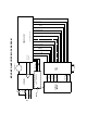
Amplifier User Panel (rear of loudspeaker):
The user panel is divided into two main sections: AC power and audio input.
The AC power is applied to the system via a L6-20 twist-lock, IEC 309,
Powercon, or VEAM connector.
MP-2 amplifiers use 6 amp breakers
MP-4 amplifiers use 8 amp breakers
HP-2 amplifiers use 10 amp breakers
HP-4 amplifiers use 15 amp breakers
MPW-4 amplifiers use 10 amp breakers.
The audio signal is introduced to the system via a 3 or 5 pin XLR or VEAM
option.
MP amps and the SB-2 have polarity switches.
The HP amps do not have a polarity switch; pin 2 is positive.
The audio pair (pins 2 and 3) is transmitted on a ribbon cable to the control
board.
In addition, feedback lines returning from the control board on the ribbon cable
power the LED's on the User Panel.
AC Mains Board:
The AC Mains is responsible for determining the AC line voltage and applying it
to the appropriate taps on the power transformer. This module also has circuitry
for protecting the unit from dangerous power spikes and provides a soft start for
lower line loading on the power amp. If the AC Mains has a problem, it may not
supply voltage to the power transformer and the unit will not power up.
When an acceptable AC line voltage is applied to the HP/MP amplifier, the unit
should give at least 2 clicks and the green "active" LED on the front panel will
illuminate. If these conditions do not happen there is a fault impeding the AC line
voltage.
Symptom: Unit will not power up, no lights, no clicks, nothing
With the green phoenix connector attached to the AC Mains and with the AC line
voltage within normal operating spec (95 -125 VAC; 208-235 VAC) you should
hear the relays click on and see the green "active" led illuminate.
FOR 120 OR 220 VAC you should hear 3 relay clicks.
Lower voltage e.g. Japan 100VAC you will not hear the 2nd relay click.
The last relay clicking is the thermistor being taken out of circuit, which is normal.
6