
Service manual


MSL-4 to a 650-P for 2 channel MP amps;
MTS-4A to a PSW-6 for 4 channel MP amps;
M3D to MILO for 4 channel HP amps and
700HP to 600 HP for 2 channel HP amps
You will want to make note of these changes, externally on the amp and also
change the LED label on the user panel to correctly identify the LED operation.
Troubleshooting note:
It is possible that if something went wrong on this board it could stop the unit
from passing signal.
Try module swapping with a known good working unit to verify.
Power Supply Module:
The Power Supply board generates the +/-15VDC, +/- 43VDC and +/- 108VDC
power rails for the control board and the amplifier electronics. If one of these
voltages is missing or is not symmetrical to its differential opposite it can cause
DC on the output and cause the unit to fault.
Symptom:
Unit faults on power up or shuts down immediately after power up
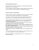
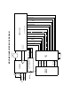
Remove the DC harness from the amp heatsink module, apply power and
measure the DC voltages on the harness coming from the Power Supply module.
- see diagram below
* Note: +/- 43VDC and +/- 108VDC are unregulated and may vary from its
typical value. This is fine as long as both positive and negative power rails are
even.
View of the DC harness as seen when connected to the amp heatsink.
Amplifier Heatsink Module:
The signal path on the HP/MP/MPW amplifiers is very simple.
8