Operating Instructions MSL-6 Self-Powered Loudspeaker System Copyright © 1997 Meyer Sound Laboratories, Inc. All rights reserved Part # 05.053.026.
Contents Introduction .......................................................... 3 AC Power .............................................................. 3 Audio Input ........................................................... 5 Amplification and Protection Circuitry ............... 6 Rigging .................................................................. 7 Measurement and System Integration ............... 8 Complete Systems ............................................ 8 Driver Troubleshooting ......
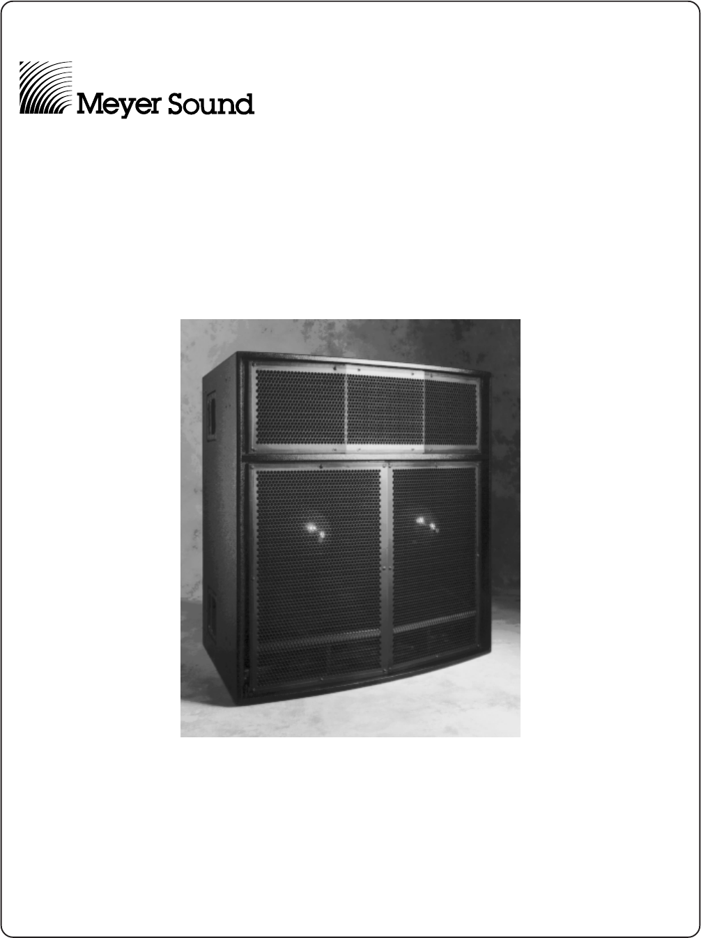
Introduction AC Power The MSL-6, Meyer Sound’s largest self-powered speaker, is ideally suited for large-scale vocal public address applications as a stand-alone system, and for musical sound reinforcement in combination with Meyer selfpowered subwoofers and/or the DS-2P mid-bass speaker. The MSL-6 features a 25° vertical coverage angle, permitting long-throw arrays with up to three vertical rows with minimal overlap between coverage areas.
If the voltage decreases below the lower bound of either operating range (brown-out), the supply uses stored energy to continue functioning briefly. The unit turns off if the voltage does not increase above the threshold before the storage circuits are depleted. The time that the MSL-6 continues to operate during brown-out depends on how low the voltage drops and the audio source level during this period.
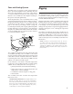
Safety Issues Audio Input Pay close attention to these important electrical and safety issues. The MSL-6 presents a 10 kΩ balanced input impedance to a three-pin XLR connector wired with the following convention: Use a power cord adapter to drive the MSL-6 from a standard 3-prong outlet (NEMA 5-15R;125 V max). earth ground chassis ground The MSL-6 requires a grounded outlet. Always use a grounding adapter when connecting to ungrounded outlets.
Amplification and Protection Circuitry The MSL-6 is powered by the Meyer MP-4, a fourchannel 2480 W amplifier (620 W/ch) utilizing complementary power MOSFET output stages (class AB/H). The following sections discuss the MP-4’s limiting circuitry and four-fan cooling system. The TruPower™ Limiting System Conventional limiters assume that the resistance of a speaker remains constant and set the limiting threshold by measuring voltage only.
Fans and Cooling System Rigging The MSL-6 uses a forced-air cooling system with four fans to prevent the amplifiers from overheating. The fans draw air in through ducts on the front of the cabinet, over the heatsinks, and out the rear of the cabinet. Since dust does not accumulate in the amplifier circuitry, its life-span is increased significantly. The front grill surface acts as an air filter for the cooling system and should always be in place during operation.
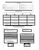
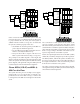
Measurement and System Integration Complete Systems Meyer Speaker Types Measurement and correction tools are required to assemble a complete sound system, particularly when the venue requires precise array design, delay systems, or compensation for significant reverberation.
LD-1A CH 1 LD-1A CH 1 Ch A CP-10 EQ Ch B Input Mid-Hi Output Ch A CP-10 EQ Ch B MSL-6 Upper Input A Sub Output B A Sub Output B Input Input MSL-6 Lower Input MSL-6 Lower Output CH 3 Output CP-10 EQ CH 3 CP-10 EQ MSL-6 Upper DS-2 Output Delay Delay Mid-Hi Output Input Output CH 5 Output CH 5 MSL-4 Down-fills DS-2P 650-P Subwoofers MSL-4 Down-fills 650-P Subwoofers CH 5 controls the MSL-4 down-fill system.
Driver Troubleshooting The Remote Monitoring System (RMS) is the best method to query the status of the drivers in a system before and during the performance. RMS monitors peak power, peak voltage, and average voltage (VU) for each amplifier channel, allowing immediate detection and muting for drivers with open or shorted voice coils, with minimal disruption to the system. Contact Meyer Sound for more information about RMS.
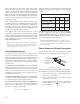
Use the following test to verify polarity between high and low frequency drivers: 1. Place a monitoring microphone 5 ft from the grill frame, 24” below the top of the cabinet, at the midpoint between low drivers (center-line of cabinet). 2. Connect a signal source to the loudspeaker and note the frequency response. The polarity is correct if the frequency response is ±3 dB 500 Hz – 1 kHz. Polarity reversal is indicated by a 6 – 12 dB cancellation in the same range.
Dimensions All units in inches 26.9 14.0 3.1 12.5 24.2 0.5 C.G. 30.4 29.4 Ref C.G. 42.8 22.0 1.6 7.4 32.2 Top 12.5 42.5 32.3 Front Side (Rigging Typ, both ends) Physical Construction Upper & Lower Braces 3⁄16" Steel, ASTM A36 3⁄8"-16 Reinforcement Pivoting Lift Ring 1500 lb.
Safety Summary English ! Français • To reduce the risk of electric shock, disconnect the loudspeaker from the AC mains before installing audio cable. Reconnect the power cord only after making all signal connections. • Pour réduire le risque d’électrocution, débrancher la prise principale de l’haut-parleur, avant d’installer le câble d’interface allant à l’audio. Ne rebrancher le bloc d’alimentation qu’après avoir effectué toutes les connections.
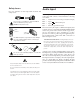
Controls and Connectors ! WARNINGS: THIS PRODUCT MUST BE GROUNDED This surface may reach high temperatures while in use. To ensure proper operation, allow at least 6 inches clearance from this surface and adequate ventilation. To reduce the risk of electric shock do not remove cover. No operator serviceable parts inside. Refer servicing to qualified personnel. To reduce the risk of fire or electric shock do not expose this appliance to rain or moisture.