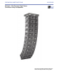
OPERATING INSTRUCTIONS M SERIES M’elodie™ UltraCompact High-Power Curvilinear Array Loudspeaker Keep these important operating instructions. Check www.meyersound.com for updates.
DECLARATION OF CONFORMITY ACCORDING TO ISO/IEC GUIDE 22 AND EN 45014 Operation is subject to the following two conditions: (1) this device may not cause harmful interference, and (2) this device must accept any interference received, including interference that may cause undesired operation. European Contact: Your local Meyer Sound dealer or Meyer Sound Germany, GmbH. Carl Zeiss Strasse 13, 56751 Polch, Germany. Telephone: 49.2654.9600.58 Fax: 49.2654.9600.
SYMBOLS USED These symbols indicate important safety or operating features in this booklet and on the chassis: Dangerous voltages: risk of electric shock Important operating instructions Frame or chassis Protective earth ground Pour indiquer les risques résultant de tensions dangereuses Pour indequer important instructions Masse, châssis Terre de protection Zu die gefahren von gefährliche spanning zeigen Zu wichtige betriebsanweisung und unterhaltsanweisung zeigen Rahmen oder chassis Die schutze
SAFETY SUMMARY English - - - - - - To reduce the risk of electric shock, disconnect the loudspeaker from the AC mains before installing audio cable. Reconnect the power cord only after making all signal connections. Connect the loudspeaker to a two-pole, three-wire grounding mains receptacle. The receptacle must be connected to a fuse or circuit breaker. Connection to any other type of receptacle poses a shock hazard and may violate local electrical codes.
CONTENTS INTRODUCTION 1 CHAPTER 1: Introducing the M’elodie™ Loudspeaker 3 Advanced M’elodie Technology Integrated Amplifier and Processing Truck-Smart and Rig-Ready Total System Approach 3 3 4 5 CHAPTER 2: Power Requirements 7 AC Power Distribution Looping and Cabling Power Connector Wiring Conventions Voltage Requirements Current Requirements Electrical Safety Issues 7 7 8 8 9 10 CHAPTER 3: Amplification and Audio Audio Input Amplification and Protection Circuitry M’elodie Interconnections Cabling
Using M’elodie with the 700-HP Subwoofer Using M’elodie with the 600-HP Subwoofer CHAPTER 6: System Design and Integration tools Meyer Sound MAPP Online Pro™ SIM® 3 Measurement System Source Independent Measurement Technique Applications CHAPTER 7: QuickFly® Rigging M’elodie GuideALinks Front GuideALinks The MG-M’elodie Multipurpose Grid Using the MG-M’elodie for Ground-Stacking The MTF-MICA/M’elodie Transition Frame MCF-M’elodie Caster Frame APPENDIX A: Optional Rain Hood Installing the M’elodie Quick-C
INTRODUCTION INTRODUCTION These operating instructions provide important information about the form, features, function, and specifications of the M’elodieTM ultracompact high-power curvilinear array loudspeaker. In addition to power requirements and audio characteristics, the book also covers fundamental line array design, useful software tools, and rigging options for M’elodie. Chapter 1: Introducing M’elodie provides a general description of M’elodie and its capabilities and functionality.
INTRODUCTION 2
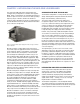
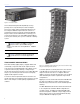
CHAPTER 1 CHAPTER 1: INTRODUCING THE M’ELODIE LOUDSPEAKER The self-powered M’elodie ultracompact high-power curvilinear array loudspeaker is a member of the popular MILO® family of loudspeakers. Its extended high-frequency headroom gives it a smooth sound over its wide operating frequency range of 70 Hz to 18 kHz. This headroom combines with a 100-degree horizontal coverage pattern to provide detailed resolution of delicate transient information across a broad coverage area. Figure 1.1.
CHAPTER 1 Figure 1.2. M’elodie amplifier This modular, field-replaceable amplifier/processing package also incorporates Meyer Sound’s Intelligent AC™ power supply, which automatically adjusts for any line voltage worldwide and provides both soft turn-on and transient protection. M’elodie is fitted standard with Meyer Sound’s exclusive RMS interface, allowing you to monitor and troubleshoot an entire RMS-equipped Meyer Sound system remotely from your PC notebook or desktop system.
CHAPTER 1 TOTAL SYSTEM APPROACH M’elodie integrates seamlessly with other Meyer Sound products. With compatible acoustical and performance characteristics and dedicated QuickFly rigging hardware, M’elodie, MICA, MILO, and other Meyer Sound selfpowered loudspeakers can provide you with everything you need to design and implement systems for optimum performance in venues of any size or shape.
CHAPTER 1 Figure 1.7. The 600-HP high-power subwoofer M’elodie is supported by Meyer Sound’s MAPP Online Pro acoustical prediction program and the Galileo™ loudspeaker management system. Once a M’elodie system is designed and installed, its performance can be confirmed using a SIM 3 audio analyzer system.
CHAPTER 2 CHAPTER 2: POWER REQUIREMENTS Looping Audio Input LOOPING AND CABLING10k Ω Balanced y iv it k et All audio components (self-powered loudspeakers, mixing consoles, processors, etc.) must be properly connected to the AC power distribution, preserving AC line polarity and connecting earth ground such that all grounding points are connected to a single node or common point using the same cable gauge as the neutral and line(s) cable(s).
CHAPTER 2 The blue connector serves as the input for all the units looped in that circuit and it is rated to 20 amps maximum. Please make sure never to exceed 20 amps on any single connector. Please refer to Table 2.1. Table 2.
CHAPTER 2 TIP: Since M’elodie does not require a dedicated neutral, it can tolerate elevated voltages from ground and can be connected between line-line terminals in a 120 V 3-phase Wye system. This results in 208 V AC between lines (nominal) and will therefore draw less current for the same output power compared to operating M’elodie from 120 V AC (line-neutral). Make sure that the voltage remains within M’elodie’s recommend operating window (180 V AC to 250 V AC).
CHAPTER 2 NOTE: For best performance, the AC cable voltage drop should not exceed 10 volts, or 10 percent at 115 volts and 5 percent at 230 volts. Make sure that even with the AC voltage drop, the AC voltage always stays in the operating windows. The minimum electrical service amperage required by a M’elodie system is the sum of each loudspeaker’s maximum long-term continuous current. An additional 30 percent above the minimum amperage is recommended to prevent peak voltage drops at the service entry.
CHAPTER 3 CHAPTER 3: AMPLIFICATION AND AUDIO More than just a self-powered loudspeaker, M’elodie uses sophisticated amplification and protection circuitry and an advanced limiting system to produce consistent and predictable results in any system design. This chapter will help you understand and harness the power of the M’elodie loudspeaker’s amplifier and audio systems. Audio signals can be daisy-chained using the loop output connector on the user panel of the M’elodie loudspeaker (Figure 3.1).
CHAPTER 3 THE LIMITING SYSTEM NOTE: For details on the M’elodie loudspeaker’s audio input characteristics and amplification, see Appendix C. Low- and Mid-Frequency Limiters The M’elodie loudspeaker’s left and right 8-inch cone drivers are powered by separate amplifier channels, each with a detector but routed to one limiter; the limiter tracks both channels and uses the higher of the two values to engage.
CHAPTER 3 M’elodie is performing within its acoustical specifications and operating at a normal temperature if the limit LEDs are lit for no longer than two seconds, and then go off for at least one second. If an LED remains on for longer than three seconds, that channel enters hard limiting, with the following negative consequences: ■ Increasing input level will not increase volume. ■ Distortion increases due to clipping and nonlinear driver operation.
CHAPTER 3 14
CHAPTER 4 CHAPTER 4: RMS REMOTE MONITORING SYSTEM RMS is a real-time monitoring system that connects Meyer Sound self-powered loudspeakers with a Windows-based PC at the sound mix position or other location. Optional RMS software delivers extensive status and system performance data from every installed loudspeaker. M’elodie is RMS-ready and fitted standard with an RMS communication board installed in its user panel.
CHAPTER 4 Service LED (Red) Activity LED (Green) The Service LED blinks every two seconds to indicate that the network hardware is operational, but the loudspeaker is not installed (commissioned) on the network. When the loudspeaker has been commissioned the Activity LED will flash continuously. When the Activity LED is unlit the loudspeaker has not been installed on the network.
CHAPTER 5 CHAPTER 5: LINE ARRAYS AND SYSTEM INTEGRATION HOW LINE ARRAYS WORK Line arrays achieve directivity through constructive and destructive interference. For example, consider one loudspeaker with a single 12-inch cone radiator in an enclosure.
CHAPTER 5 6 M’elodie Cabinets 12 M’elodie Cabinets 18 M’elodie Cabinets ■ Vertical Splay Angles. Changing the splay angles between cabinets has a significant impact on vertical coverage for the high frequencies, with the result that narrower vertical splay angles produce a higher Q vertical beamwidth, while wider splay lowers the Q at high frequencies. In general, the splay angles do not affect the vertical coverage at lower frequencies. ■ Horizontal Coverage.
CHAPTER 5 Low-Frequency Design Strategies While wave guides provide isolated control over various mid- to high-frequency coverage areas, the low-frequency section of a M’elodie array still requires mutual coupling — with equal amplitude and phase — to achieve better directionality. Low-frequency directionality is less dependent on the array’s relative splay angles and more dependent on the number of elements of the array.
CHAPTER 5 The block diagram below (Figure 5.3) shows one method of driving this example array, along with subwoofers (not in the MAPP Online Pro predictions). CAUTION: This example is not meant to be used as a template for your own system designs. Acoustical characteristics, physical constraints, audio content, audience, and other relevant factors should always be uniquely weighed into your own applications on a project basis.
CHAPTER 5 Using Meyer Sound Processors to Drive and Optimize the Array The Galileo 616 loudspeaker management system and the LD-3 compensating line driver are specifically designed to allow you to follow these optimization strategies: ■ The array can be divided in zones. ■ The atmospheric correction capabilities of these processors compensates for the air absorption of the air at high frequencies.
CHAPTER 5 NOTE: When precise array design, subwoofer integration, DSP and delay systems, and compensation for acoustical conditions all come into play, measurement and correction tools are a must. Meyer’s SIM 3 measurement system, Galileo, LD-3, CP-10 parametric equalizer and the VX-1 program equalizer are highly recommended. USING M’ELODIE WITH SUBWOOFERS A M’elodie system will provide full bandwidth frequency range down to 70 Hz.
CHAPTER 6 CHAPTER 6: SYSTEM DESIGN AND INTEGRATION TOOLS Meyer Sound offers two comprehensive tools to assist you with the acoustical and functional requirements of system design and optimization. This chapter introduces you to MAPP Online Pro, Meyer Sound’s powerful online acoustical prediction tool, and SIM 3, a robust instrumentation package for system measurement, analysis, and more.
CHAPTER 6 The key to MAPP Online Pro’s value is the accuracy of its predictions. Performance predictions for each Meyer Sound loudspeaker found in MAPP Online Pro are based on a model of that product built from 360 1/48th-octave–band measurements taken with a SIM audio analyzer in our anechoic chamber. The extreme consistency found from cabinet to cabinet in Meyer Sound products guarantees that the predictions MAPP Online Pro makes from this highresolution data will closely match actual performance.
CHAPTER 7 CHAPTER 7: QUICKFLY RIGGING M’elodie loudspeakers feature Meyer Sound’s QuickFly rigging system with rugged, reliable and simple components. QuickFly facilitates deploying the loudspeakers in a variety of applications. M’elodie is designed to be rigged using professional components, and its custom front and rear GuideALinks rigidly couple the individual M’elodie enclosures for flying, stacking, or transporting in stacks while still in various splayed positions.
CHAPTER 7 The rear GuideALinks permit 12 splay angles between 0 and 11 degrees in 1-degree increments. The GuideALink has four rows each with 3 columns. The splay angle between cabinets increases by one degree as the GuideAlink is pinned in adjacent positions from front to back and top to bottom.
CHAPTER 7 MAXIMUM DOWN-TILT MAXIMUM UP-TILT LOAD RATINGS GROUND STACK FRONT LINK STOW 5:1 1550 lbs 702 kg (25 M’elodie) STOW 7:1 DO NOT EXCEED 1116 lbs +/- 60 DEG.
CHAPTER 7 MCF-M’ELODIE CASTER FRAME The MCF-M’elodie Caster Frame (Figure 7.11) allows you to transport stacks of up to five M’elodie enclosures. The M’elodie GuideALinks connect the enclosures securely to the frame, allowing the convenient transport of straight or splayed stacks of M’elodie. The steel frame surrounding the board facilitates the use of forklifts. Figure 7.9. 600-HP and M’elodie in the same flown array Figure 7.11.
A B -10º B A A B CHAPTER 7 11 9 6 3 0 CAUTION: Do not exceed five M’elodie cabinets high to avoid tipping over the stack. Use position 5 11 9 6 3 0 11 CAUTION: Avoid moving the M’elodie stack in the front-to-back direction of the loudspeakers (the long side); always move the stack sideways to avoid tipping it over. 9 6 3 0 11 9 6 3 0 Figure 7.14. First M’elodie at 0 degrees (straight-up) with respect to the MCF-M’elodie 11 9 6 3 0 11 9 Use position 0 6 3 0 11 9 6 3 0 Figure 7.15.
CHAPTER 7 Figure 7.15. Transporting M’elodie enclosures with the MG-M’elodie installed on the top of the stack CAUTION: When using the MCF-M’elodie caster frame to ground-stack M’elodie loudspeakers, make sure all four caster wheels are blocked to prevent the stack from rolling away. Other rigging accessories, as well as a range of rugged protective transport covers, are available. For more information, please visit www.meyersound.com.
APPENDIX A APPENDIX A: OPTIONAL RAIN HOOD In weather-protected versions, a rain hood is included to safeguard the user panel and connectors from the elements. INSTALLING THE M’ELODIE QUICK-CLIP RAIN HOOD 1. Check the rain hood to assure that the gasket material is firmly attached along all the inner edges. If not installed, install the gasket to the rain hood; do not install the gasket to the user panel. 2.
APPENDIX B APPENDIX B: OPTIONAL VEAM MULTIPIN CONNECTOR The M’elodie loudspeaker requires a grounded outlet. It is very important that the system be properly grounded in order to operate safely and properly. Figure B.1 illustrates correct wiring for the creation of power cables and distribution systems for M’elodie loudspeakers shipped from the factory with the VEAM multipin connector. line (brown) ground (green/yellow) neutral (blue) Figure B.1. VEAM multipin connector power pin-out Figure B.2.
APPENDIX C APPENDIX C: M'ELODIE SPECIFICATIONS AND DIMENSIONAL DRAWINGS ACOUSTICAL Note: The low-frequency power response of the system will increase according to the length of the array. Operating frequency range 70 Hz - 18 kHz Note: Recommended maximum operating frequency range. Response depends upon loading conditions and room acoustics. Free field frequency response 76 Hz - 16 kHz ±4 dB Phase response 1.
APPENDIX C AUDIO INPUT Type Differential, electronically balanced Max.
APPENDIX C PHYSICAL Enclosure Premium birch plywood Finish Black textured Protective grille Powder-coated, hex-stamped steel, black mesh Rigging QuickFly rigging with four captive GuideALinks in the bottom corners of two aluminum and steel end frames, secured with quick-release pins Dimensions 28.54 w x 9.19 h x 12.75 d (724.84 mm x 233.31 mm x 323.85 mm) Weight Weight 62 lbs (28.12 kg) 6.30 [160.02 mm] 9.19 [233.31 mm] 7.08 [179.91 mm] 4.10 [104.14 mm] 26.48 [672.52 mm] 28.54 [724.
APPENDIX C 36
Meyer Sound Laboratories Inc. 2832 San Pablo Avenue Berkeley, CA 94702 www.meyersound.com T: +1 510 486.1166 F: +1 510 486.8356 © 2006 Meyer Sound Laboratories Inc. 05.152.005.