Operating Instructions UPA-P Series UPA-1P and UPA-2P Self-Powered Loudspeakers (Serial Numbers 981000 and above) UPA-1P Copyright © 1997 Meyer Sound Laboratories, Inc. All rights reserved Part #: 05.054.017.01 Rev B Keep these important operating instructions.
Contents Introduction .................................................. AC Power .................................................... The Modular Rear Panel .................................. Amplification, Limiting, and Cooling System ........ Rigging ......................................................... Full-Range Systems ........................................ 3 4 5 6 7 7 Verifying Driver Polarity ................................ 9 Troubleshooting .........................................
Introduction The Integrated Design The Meyer UPA-P Series (UPA-1P, UPA-2P) self-powered loudspeakers are comprised of: • one 12-inch cone driver and one 3-inch diaphragm compression driver; • phase-corrected, optimized control electronics; • a two-channel amplifier (350 Wrms/ch). The drivers, control electronics, and amplifier are integrated into a compact, trapezoidal enclosure.
AC Power The UPA-P uses a PowerCon locking 3-pole AC mains connector that prevents inadvertent disconnection. The unit must have the correct power plug for the AC power in the area in which it will be used. Engagement Current Requirements 2 1 3 When AC power is applied to the UPA-P, the Intelligent ACtm supply automatically selects the correct operating voltage, allowing the UPA-P to be used internationally without manually setting voltage switches.
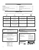
Use the table below as a guide to select cables and circuit breakers with appropriate ratings for your operating voltage. UPA-P Current Ratings Keep all liquids away from the UPA-P to avoid hazards from electrical shock. 115V 230V 100V Idle RMS 0.25 ARMS 0.13 ARMS 0.3 ARMS Max. Continuous RMS 2.8 ARMS 1.4 ARMS 3.2 ARMS Max. Burst RMS 3.2 ARMS 1.6 ARMS 3.7 ARMS Max. Peak During Burst 5.0 ARMS 2.5 ARMS 5.
Looping Audio Input Module This standard module uses a balanced, female XLR connector for audio input and a male XLR loop connector to interconnect multiple speakers. The audio input connector is hardwired with pin 2 hot to comply with audio industry standards. The loop connector, wired in parallel to the audio input, transmits the input signal if the UPAP is turned off for any reason. Summing Audio Input Module This module has two balanced female XLR connectors.
a safe level to prevent the system from overheating. Under high temperature conditions the output level is reduced 6 dB. When the heatsink temperature decreases to 75°C (167°F), the On/Temp. LED changes from red to green and the limiter threshold returns to normal. The heatsink reaches temperatures up to 185°F (85°C) during normal operation. Use extreme caution when approaching the rear of the cabinet.
vidual speaker, the power at the center of the array increases, but the coverage overlap between adjacent speakers causes comb filtering and other frequency response variations. These documents are also available on the Meyer Sound website: http://www.meyersound.com. As the splay angle increases toward the coverage angle, the power at the center of the array decreases, but the variations in frequency response diminish.
For a high power, compact system, we recommend using two UPA-2Ps and two USW-1Ps. This array provides < 143 dB SPL across 60° of horizontal coverage Verifying Driver Polarity Incorrect driver polarity impairs system performance and may damage the drivers. All Meyer loudspeakers are shipped with the drivers in correct alignment. If the driver or circuit wiring has been removed or disassembled it is essential to check the polarity between drivers and between adjacent loudspeakers.
Polarity within a UPA-P Use the following test procedure to verify polarity between drivers in the same loudspeaker: 1. Place a measurement microphone 1 meter from the front of the loudspeaker at the midway point between the low and high frequency drivers. 2. Connect a full range signal to the loudspeaker andnote the frequency response. The polarity is correct if the frequency response is smooth through the crossover region (800 Hz to 1.5 kHz).
The audio produced by the speaker is highly compressed and the limit light is constantly yellow. 1. Turn down the level of the input signal to the speaker system. Only the high or low driver seems to produce sound. 1. Make sure the audio signal is full-range and has not been filtered in a previous stage of the signal chain. If possible, monitor the audio source with highquality headphones. 2. Send the audio signal to another speaker to insure that the signal is full-range.
Safety Summary English • To reduce the risk of electric shock, disconnect the loudspeaker from the AC mains before installing audio cable. Reconnect the power cord only after making all signal connections. • Connecttheloudspeakertoatwo-pole,threewiregroundingmains receptacle. The receptacle must be connected to a fuse or circuit breaker. Connection to any other type of receptacle poses a shock hazard and may violate local electrical codes.
Rear Panel and Optional Modules The user panel and optional modules are described on page 5 of this guide. User Panel with RMS option and Standard Looping Audio Input Module.
Dimensions (in inches) 7.7 CL 2.6 7.25 12.8 7.5 14.3 14.5 30 UPA-P Back UPA-P Top 7.25 7.4 10.85 10.85 UPA-1P Side UPA-2P Side 22.4 UPA-1P Front UPA-2P Front Center of gravity represented by " 22.
Notes #
Contact Information Meyer Sound Laboratories, Inc. 2832 San Pablo Avenue Berkeley, California 94702 Telephone: 510 - 486 - 1166 FAX: 510 - 486 - 8356 E-mail: techsupport@meyersound.com http://www.meyersound.