USM-P Series Self-Powered Loudspeaker Systems OPERATING INSTRUCTIONS OPERATING INSTRUCTIONS USM-1P USM-100P Superior engineering for the art and science of sound. Keep these important operating instructions.
CONTENTS Safety Summary Introduction and Technical Advantages AC Power The Modular Rear Panel Amplification, Limiting, and Cooling System Coverage Verifying Driver Polarity Troubleshooting Specifications Rear Panel and Input Modules Drawings Dimensions and Contact Information 3 4 4 6 6 7 8 8 10 11 12 SYMBOLS USED THESE SYMBOLS INDICATE IMPORTANT SAFETY OR OPERATING FEATURES IN THIS BOOKLET AND ON THE CHASSIS.
! ENGLISH • To reduce the risk of electric shock, disconnect the loudspeaker from the AC mains before installing audio cable. Reconnect the power cord only after making all signal connections. • Connect the loudspeaker to a twopole, three wire grounding mains receptacle. The receptacle must be connected to a fuse or circuit breaker. Connection to any other type of receptacle poses a shock hazard and may violate local electrical codes.
USM-P: INTRODUCTION AND TECHNICAL ADVANTAGES Thank you for investing in the Meyer Sound USM-P Series. The USM-100P and USM-1P self-powered stage monitors are composed of: horn's wider pattern (100°H x 40°V) provides broad coverage in either wedge or flown applications. • one 15-inch cone driver and one 3inch diaphragm compression driver; • phase-corrected, optimized control electronics; • a two-channel amplifier (350Wrms/ch).
! Continuous voltages higher than 264V may damage the unit. VOLTAGE REQUIREMENTS The USM-P operates safely and without audio discontinuity if the AC voltage stays within the range 88-264V, 4763Hz. After applying AC power, the system is muted while the circuitry charges up and stabilizes. After two seconds, the On/Temp. LED on the user panel illuminates green, the system unmutes and is ready to pass audio signals. If the On/Temp.
THE MODULAR REAR PANEL The rear panel of the USM-P has two slots for processor modules. The top slot contains the Audio Input and Control Module; the bottom slot contains the optional Remote Monitoring System™ (RMS) Module. A blank plate covers the bottom slot if RMS is not installed. For drawings of these modules, see page 11. AUDIO INPUT There are three, interchangeable Audio Input and Control Modules with optimized connectors and controls for different applications.
AMPLIFIER NATURAL CONVECTION COOLING SYSTEM The USM-P employs a natural convection cooling system that depends on air flow from below the cabinet over the heatsink. Allow for proper ventillation of fresh air when using the speaker. If the temperature of the heatsink reaches 85°C (185°F), the On/Temp. LED on the rear panel turns from green (On) to red (Temp.) and the limiter threshold is lowered to a safe level to prevent the amplifiers from overheating.
VERIFYING POLARITY Incorrect driver polarity impairs system performance and may damage the drivers. All Meyer Sound loudspeakers are shipped with the drivers in correct alignment. If the driver or circuit wiring has been removed or disassembled it is essential to check the polarity between adjacent monitors and between drivers and between adjacent loudspeakers. POLARITY IN ADJACENT LOUDSPEAKERS 4. Apply the same signal to the second speaker with the first speaker still connected.
THE AUDIO PRODUCED BY THE SPEAKER IS DISTORTED OR COMPRESSED BUT THE LIMIT LIGHT IS NOT ILLUMINATED. 1. Make sure the XLR cable is securely fastened to the XLR audio input connector. 2. Send the audio signal to another speaker to insure that the level is within the proper range. Turn the source level down before reconnecting the audio input and increase the level slowly to avoid a sudden blast of sound. 3. Monitor the audio source with headphones.
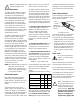
USM-1P/100-P SPECIFICATIONS Acoustical 1 (each loudspeaker) Operating Frequency Range2 Free Field Half-Space3 Phase Response4 Maximum Peak SPL5 Signal to Noise Ratio 30 Hz - 20 kHz 44 Hz - 16 kHz ±3 dB; -6 dB at 40 Hz and 20 kHz 40 Hz - 16 kHz ±3 dB; -6 dB at 33 Hz and 20 kHz ±35° 500 Hz - 16 kHz; +90° at 120 Hz 132 dB >95 dB (A-weighted noise floor to max SPL) Co ver a g e USM-100P USM-1P -6 db at 100° H x 40° V; -10 dB at 120° H x 60° V -6 db at 45° H x 45° V; -10 dB at 60° H x 60° V Cr osso ver US
USER PANEL AND OPTIONAL MODULES The user panel and optional module are described on page 6 of this document.
PHYSICAL DIMENSIONS All units in inches. USM-1P USM-100P CONTACT INFORMATION Meyer Sound Laboratories, Inc. 2832 San Pablo Avenue Berkeley, CA 94702 tel: 510.486.1166 fax: 510.486.8356 e-mail: techsupport@meyersound.com http: www.meyersound.com 12 05.089.004.