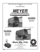
OPERATORS AND PARTS MANUAL NO. 03-6-TSS-F&R FOR 3200 & 4200 SERIES TSS VARIABLE SPEED MODEL Front & Rear Unload Forage Boxes with Independent Outfeed Clutch 3200 SERIES: Model 3216 Model 3218 Model 3220 DO NOT OPERATE EQUIPMENT UNTIL THIS MANUAL HAS BEEN READ AND UNDERSTOOD. 4200 SERIES: Model 4216 Model 4218 Model 4220 Model 4222 Manufactured by County Hwy. A West P.O. Box 405 Dorchester, Wisconsin 54425-0405 Phone 715-654-5132 • FAX 715-654-5513 1-800-325-9103 www.meyermfg.
TABLE OF CONTENTS TABLE OF CONTENTS . . . . . . . . . . . . . . . . . . . . . . . . . . . . . . . . . . . . . . . . . . . . . . . . . . . . . . . . . . . . . . . . . . . 1 MANUFACTURER’S WARRANTY . . . . . . . . . . . . . . . . . . . . . . . . . . . . . . . . . . . . . . . . . . . . . . . . . . . . . . . . . . 3 INTRODUCTION . . . . . . . . . . . . . . . . . . . . . . . . . . . . . . . . . . . . . . . . . . . . . . . . . . . . . . . . . . . . . . . . . . . . . . . . 4 SAFETY PRECAUTIONS . . . . . . . . . .
ADJUSTMENTS. . . . . . . . . . . . . . . . . . . . . . . . . . . . . . . . . . . . . . . . . . . . . . . . . . . . . . . . . . . . . . . . . . . . . . . . 25 ROLLER CHAIN DRIVES . . . . . . . . . . . . . . . . . . . . . . . . . . . . . . . . . . . . . . . . . . . . . . . . . . . . . . . . . . 28 RANGE CONTROL CLUTCH ADJUSTMENT . . . . . . . . . . . . . . . . . . . . . . . . . . . . . . . . . . . . . . . . . . 28 VARIABLE SPEED BELT REPLACEMENT . . . . . . . . . . . . . . . . . . . . . . . . . . . . . . . .
NEW MEYER (FRONT & REAR UNLOAD) FORAGE BOX Jan. 1, 1995 MANUFACTURER’S WARRANTY I. The “Product Registration & Inspection Certificate” along with the original billing invoice “Owner’s Registration Form” must be completed in full and promptly returned to Meyer Mfg. Corp. for this warranty to become both valid and effective. All warranties on New Meyer Forage Boxes shall apply only to the original retail customer from an authorized Meyer Mfg. Corp. dealership. II.
INTRODUCTION Congratulations on your purchase of a new Meyer farm equipment product. Undoubtedly you have given much consideration to your purchase and we’re proud that you have selected Meyer. Pride in craftsmanship, engineering and customer service have made Meyer products the finest in the farm equipment industry today. There is no substitute for quality. That is why thousands of people like you have purchased Meyer farm equipment.
SAFETY PRECAUTIONS This symbol is used to call attention to instructions concerning personal safety. Be sure to observe and follow these instructions. Take time to be careful! WARNING: BEFORE ATTEMPTING TO OPERATE THIS FORAGE BOX, READ AND STUDY THE FOLLOWING SAFETY INFORMATION. IN ADDITION, MAKE SURE THAT EVERY INDIVIDUAL WHO OPERATES OR WORKS WITH THE FORAGE BOX, WHETHER FAMILY MEMBER OR EMPLOYEE, IS FAMILIAR WITH THESE SAFETY PRECAUTIONS.
SAFETY FIRST A brief definition of signal words that are used in this manual is as follows: DANGER indicates an imminently hazardous situation which, if not avoided, WILL result in death or serious injury. WARNING indicates a potentially hazardous situation which, if not avoided, COULD result in death or serious injury and includes hazards that are exposed when guards are removed. CAUTION indicates a potentially hazardous situation which, if not avoided, MAY result in minor or moderate injury.
SAFETY FIRST The Meyer Forage Box is manufactured with operator safety in mind. Located on the forage box are various decals to aid in operation and warn of danger or caution areas. Pay close attention to all decals on the forage box. DO NOT REMOVE ANY DECALS. IF DECALS ARE LOST, DAMAGED OR IF FORAGE BOX IS REPAINTED, REPLACE DECALS. REMEMBER: DECALS ARE FOR YOUR PROTECTION AND INFORMATION.
WARNING: WARNING: IF FOR ANY REASON THE EMERGENCY STOP MECHANISM DOES NOT FUNCTION PROPERLY, DO NOT USE THE MACHINE UNTIL IT IS REPAIRED. FAILURE TO HEED MAY RESULT IN SERIOUS PERSONAL INJURY OR DEATH. OPERATION OF THE EMERGENCY STOP Across the upper edge of the front unloading unit is a “Warning Push For Emergency Stop” pushbar. By pushing on this bar during front unloading operation only, the forage box will shut down in an emergency.
PRE-OPERATION TRANSPORTING Be certain your forage box is properly mounted to the running gear. Consult your dealer if you have any questions about the tie down kit from the manufacturer and illustrated in the parts listing of this manual. Always disconnect the PTO drive shaft from the tractor and return it to the PTO storage bracket on the unloading unit before transporting. Failure to do this may result in equipment damage.
HOSE HOLDER BRACKET HOSE TIP HOLDER IMPORTANT: Support hoses on Hose Holder Bracket to relieve weight & stress from hose tip holder. PTO DRIVE SHAFT STORAGE HANGER PROPER PTO DRIVE SHAFT AND HYDRAULIC HOSE STORAGE Your running gear probably has a telescoping tongue for convenience to hitch up. Always back up and lock this tongue in the operating position after hitching. WARNING: YOU MUST OBSERVE ALL APPLICABLE TRAFFIC LAWS WHEN TRANSPORTING ON PUBLIC ROADWAYS.
Truck Mount Forage Boxes Depending on the make and model of truck it may be necessary to install a light converter (MEYER PART #56-0028.) Converter will allow signal lights and brake lights to operate according to DOT lighting standard. Call factory for more information. FRONT UNLOAD DRIVE COUPLER “SET-UP” (PTO OR HYDRAULIC DRIVE) WARNING: DISCONNECT PTO DRIVE SHAFT AND HYDRAULIC HOSES (RELIEVE HYDRAULIC PRESSURE) BEFORE CLEANING, ADJUSTING, LUBRICATING OR SERVICING THIS FORAGE BOX.
STEP 3 Move the lever for PTO drive rear unloading to the “Disengage” position (UP). (Shield Removed For Illustration Purposes Only) PTO DRIVE REAR UNLOAD DISENGAGE LEVER Operating Procedures: See Front Unload “VARIABLE SPEED OPERATION with IOC” Page 15 #37-0010 COUPLING PLATE ASSEMBLY COMPLETE KEY 1 2 PART NO.
REAR UNLOAD DRIVE COUPLER “SET-UP” (PTO OR HYDRAULIC DRIVE) WARNING: DISCONNECT PTO DRIVE SHAFT AND HYDRAULIC HOSES (RELIEVE HYDRAULIC PRESSURE) BEFORE CLEANING, ADJUSTING, LUBRICATING OR SERVICING THIS FORAGE BOX. FAILURE TO HEED MAY RESULT IN SERIOUS PERSONAL INJURY OR DEATH. STEP 1 Install Coupling Plate and lynch pin onto the large gearbox assembly on the splined shaft at the REAR of the forage box.
STEP 3 Move the Independent Outfeed Clutch lever to “STOP” (UP). NOTE: The PTO driven independent outfeed clutch can be used to clean out accumulation of forage from the front unit cross conveyor without changing the drive coupler for forage box rear unloading. INDEPENDENT OUTFEED CLUTCH LEVER STEP 4a (PTO DRIVE) or Move the lever for PTO drive rear unloading to the “ENGAGE” position (DOWN).
FRONT UNLOAD VARIABLE SPEED OPERATION WITH INDEPENDENT OUTFEED CLUTCH DECAL #46-0001-64 FORAGE BOX CONTROL LEVERS WARNING: NEITHER THE VARIABLE SPEED NOR THE HI-LO RANGE CONTROL LEVER WILL DISENGAGE THE CROSS CONVEYOR. ONLY THE TRACTOR PTO, INDEPENDENT OUTFEED CLUTCH, OR EMERGENCY STOP MECHANISM WILL STOP THE CROSS CONVEYOR . FAILURE TO HEED MAY RESULT IN SERIOUS PERSONAL INJURY OR DEATH. Facing the front of the forage box, the lower most RH control lever is the INDEPENDENT OUTFEED CLUTCH control.
UNLOADING THE FORAGE BOX START UP PROCEDURES Pull the forage box into position and park so that the cross conveyor discharge opening is in alignment with the silo filling blower hopper. If the forage box is equipped with a fold down cross conveyor extension, it can be lowered before pulling in front of the blower. After a couple of parking trails, you may become familiar with the correct parking place and be able to lower the cross conveyor extension after parking.
Slow up, but do not stop the VARIABLE SPEED control when shifting to “HI” RANGE. SHUTDOWN PROCEDURES CAUTION: YOU CAN MOVE THE RANGE CONTROL LEVER TO “HI” FOR CLEAN-OUT AT THE END OF UNLOADING AND YOU MAY ALSO FIND IT TO BE AN APPROPRIATE SPEED SELECTION FOR SMALL OR PARTIAL LOADS. DO NOT START AND UNLOAD FULL LOADS IN “HI” RANGE.
REAR UNLOAD OPERATION PTO OR HYDRAULIC DRIVE WARNING: MAKE CERTAIN EVERYONE IS WELL CLEAR OF EQUIPMENT BEFORE APPLYING POWER. FAILURE TO HEED MAY RESULT IN SERIOUS PERSONAL INJURY OR DEATH. Always park the forage box and unloading tractor in a straight line. Minimize the unloading angle on the PTO drive shaft to prevent wearing of universal joints when connected to the unloading tractor PTO. Shift the unloading tractor to “Neutral” or “Park” and set the brakes.
WARNING: DO NOT STEP UP ON ANY PART OF THE FORAGE BOX AT ANY TIME. FAILURE TO HEED MAY RESULT IN SERIOUS PERSONAL INJURY OR DEATH. When finished unloading, reduce engine speed to idle and disengage the tractor PTO or hydraulics. Pull the forage box straight ahead to pull the rear door away from the unloaded pile of forage. Gravity will allow the rear door to swing shut. The rear door latches will engage to secure it closed. Visibly observe that rear discharge door properly latches close.
LUBRICATION WARNING: DISCONNECT PTO DRIVE SHAFT (OR HYDRAULIC POWER SOURCE) BEFORE CLEANING, ADJUSTING, LUBRICATING OR SERVICING THIS MACHINE. FAILURE TO HEED MAY RESULT IN SERIOUS PERSONAL INJURY OR DEATH. DAILY LUBRICATION (every 8-10 loads) Grease (2) PTO drive shaft universal joints (not illustrated). Grease (1) PTO drive shaft telescoping shaft and tube. Zerk accessible through the plastic guards (not illustrated). Grease front idler sprocket - wipe off excess grease from exterior.
END OF CROP CLEANUP AND MAINTENANCE Allow box to completely clean out last load of forage. Clean out all forage material from inside the box, roof and on the outside of the box. Clean the front cross conveyor on the top pan and in the lower pan (chain return) area. Clean out the clean-out panel. Clean out the deflector shield at the rear of the box, both inside and outside. It is recommended to lube the forage box before storage to exclude moisture from bearings.
TWO-SPEED OPERATION CONTROL LEVER NOTE: Normal operation is using a tractor. If using some other vehicle exercise equivalent caution when parking and exiting this vehicle. WARNING: THE RANGE CONTROL LEVER DOES NOT STOP THE CROSS APRON. ONLY THE TRACTOR PTO OR THE EMERGENCY STOP MECHANISM WILL STOP THE CROSS CONVEYOR. FAILUR E TO H EED MAY RESULT IN SER I O U S PERSONAL INJURY OR DEATH.
NOTE: The INDEPENDENT OUTFEED CLUTCH and HI-LO RANGE control levers must be in their “Stop” or “Neutral” positions when engaging and disengaging the PTO drive shaft (or optional hydraulic drive). All forage box control lever selections are to be made while the PTO (or hydraulic) power is in operation. If the control levers are engaged before power is applied, damage may occur to the Independent Outfeed Clutch drive.
TWO SPEED LUBRICATION AND MAINTENANCE WARNING: DISCONNECT PTO DRIVE SHAFT (OR OPTIONAL HYDRAULIC POWER SOURCE) BEFORE CLEANING, ADJUSTING, LUBRICATING OR SERVICING THIS MACHINE. FAILURE TO HEED MAY RESULT IN SERIOUS PERSONAL INJURY OR DEATH. ROLLER CHAIN DRIVES Oil roller chains on auger drive and cross conveyor drive. Oil through slots provided in the chain shields. The roller chain drives are tensioned by automatic spring loaded tension blocks.
ADJUSTMENTS WARNING: DISCONNECT PTO DRIVE SHAFT (OR HYDRAULIC POWER SOURCE) BEFORE CLEANING, ADJUSTING, LUBRICATING OR SERVICING THIS MACHINE. FAILURE TO HEED MAY RESULT IN SERIOUS PERSONAL INJURY OR DEATH. CLEAN-OUT PANEL Remove clean-out panel on a regular basis to clean out accumulation of foreign material build-up. Keep this area clean for proper cross conveyor chain operation.
ADJUSTMENT of 3200-4200 SERIES MAIN APRON CHAINS PRIOR TO 08 SERIAL #’S ONE APRON SLAT FRONT REAR 2" SHACKLE BRACKET FRONT WOOD SLIDE RAIL 10" STRINGER ANCHORING EYE BOLT REAR WOOD SLIDE RAIL (Left Hand Side - Side View) - typical both sides A.
ADJUSTMENT of 3200-4200 SERIES MAIN APRON CHAINS 08 SERIAL #’S & LATER FRONT 2" ONE APRON SLAT SPRING LOADED TENSIONER REAR FRONT SLIDE RAIL TENSIONER ROD 10" STRINGER REAR SLIDE RAIL (Left Hand Side - Side View) - typical both sides A. For Regular Tightening: 2. Allows to Equalize Stretch in Individual Chain Strand Pairs of each Main Apron.
ROLLER CHAIN DRIVES VARIABLE SPEED CONTROL ADJUSTMENT All roller chain drives are tensioned by automatic spring loaded tension blocks. When the Variable Speed control lever is in “NEUTRAL,” neither the main aprons nor the unloading augers are to operate when under load - (when wagon is full of forage). Variable speed operation should begin when the lever is moved down one or two notches from “NEUTRAL.
INDEPENDENT OUTFEED CLUTCH BELT REPLACEMENT 1. Move the Independent Outfeed Clutch control lever to “STOP” (up). INDEPENDENT OUTFEED CLUTCH ADJUSTMENT Lengthen or shorten linkage bolt with jam nut to create moderate tension on the Double V-Belt when engaging the Independent Outfeed Clutch control lever into the “Run” position. 2. Extend the PTO drive shaft out straight and lower the tractor end down to ground level. 3. Unlatch and raise the hinged top, front chain shield assembly. 4.
This Page Intentionally Blank.
REPAIR PARTS 3200-4200 SERIES HYDRAULIC REAR UNLOAD COMPONENTS KEY 1 2 3 PART NO. QTY 55-0099 1 55-0083 2 831-3816-1.25 4 4 5 55-0059 55-0029 1 1 6 55-0028 1 7 8 9 10 11 55-0010 55-0027 851-3816-1.
PTO REAR UNLOAD DRIVE TRAIN KEY 1 2 3 PART NO.
PTO REAR UNLOAD DRIVE CLUTCH TRUCK MOUNT ONLY KEY 1 2 3 4 5 PART NO. 14-0002-2 14-0002-3 826-1014 16-0040-3 16-0040-1 6 7 8 9 10 11 12 13 14 15 16 17 810-3816-Z 16-0043-1 23-0082 35-0016 21-0001 17-0001 35-0023 14-0036 29-0014 16-0041 25-0278-1 15-0003 18 18a 15-0005 13-0014 19 20 814-3816-Z 851-3816-1.
FRONT & REAR UNLOAD FORAGE BOX MAIN APRON CHAIN TIGHTENER PRIOR TO 08 SERIAL #’S KEY 1 2 3 4 5 6 7 8 9 10 11 12 13 14 15 16 17 18 19 20 PART NO. 25-0215 25-0211 25-0222 25-0247 25-0222-TRUCK 25-0247-TRUCK 25-0223 25-0248 25-0223-TRUCK 25-0248-TRUCK 25-0224 25-0225 25-0216 25-0220 811-5013-4Z 813-5013-Z 25-0221 851-5013-1.25Z 851-3816-1.
TSS UNIT FRAME W/ IOC IF YOUR UNIT IS OPTIONAL RH DISCHARGE, OPPOSITE TO ILLUSTRATION, SPECIFY LISTED PART NO. FOLLOWED BY -RH KEY 1 2 3 4 5 6 PART NO.
TSS CROSS CONVEYOR W/IOC KEY 1 2 3 4 5 6 PART NO. 14-0004 10-0008 14-0004-2 14-0004-3 35-0002 23-0023 QTY 2 4 8 4 5 1 7 8 10-0007 11-0111 1 1 11-0140 1 11-0060 11-0059 1 1 11-0006-1 206 9 10 3200 & 4200 Series DESCRIPTION Bearing Assembly, 1" Sprocket, No.
FRONT & REAR UNLOAD MAIN APRON KEY 1 2 3 4 5 6 7 7A 8 9 10 11 12 13 14 15 16 PART NO.
TWO SPEED CLUSTER DRIVE SPECIFY-RH FOR RH DISCHARGE. ITEMS 15, 28, 29, 40 ARE PARTS OF COMPLETE ASSEMBLY, KEY 44.
TWO SPEED CLUSTER DRIVE KEY PART NO. 1 17-0001 2 33-0012 3 4 5 6 7 8 12 13 14 15 16 17 18 19 20 21 23 24 25 26 27 28 29 30 31 QTY.
TSS VARIABLE SPEED CLUSTER DRIVE W/IOC SPECIFY-RH FOR RH DISCHARGE.
TSS VARIABLE SPEED CLUSTER DRIVE W/IOC KEY 1 2 3 4 5 6 7 8 9a 9b 10 11 12 13 14 15 16 17 18 19 20 21 22 23 24 25 26 27 28 29 30 31 32 33 34 35 36 37* 38* 39* 40 41* 42 43 44 45 46 47 48 49 50 51 52 53 54 55 PART NO.
TSS AUGERS & AUGER DRIVE IF YOUR UNIT IS OPTIONAL RH DISCHARGE, OPPOSITE TO ILLUSTRATION, SPECIFY LISTED PART NO. FOLLOWED BY -RH KEY 1 2 2A 2B 2C 3 4 5 6 7 8 9 10 11 12 13 14 15 PART NO.
3200-4200 SERIES INDEPENDENT OUTFEED CLUTCH DRIVE “STOP” & “RUN” CONTROL RELATED PARTS KEY 1 2 3 4 5 PART NO.
VARIABLE SPEED SHIFTER CONTROLS AND EMERGENCY STOP CLUTCH RELATED PARTS KEY PART NO. 13 25-0158 14 15 KEY PART NO. 1 42-0022-1 2 42-0021 3 42-0013 4 5 16-0031 16-0029 6 7 8 9 10 814-3816-Z 805-0038- Z 29-0008 42- 0020 42-0019 11 12 851-3816-2Z 827-3118-.38 QTY DESCRIPTION 2 Linkage Bar 1 Bolt w/chain& Eyelet 1 Pipe Guide Bracket Asm. 1 Speed Control Pipe 1 Speed Control Handle Asm.
TWO SPEED HI-LO SHIFTER CONTROL KEY 1 2 3 4 5 6 7 8 9 10 11 12 13 14 15 16 PART NO. 42-0022-1 851-3816-1.25Z 16-0032-2 38-0003 25-0154 814-3816-Z 805-0038- Z 29-0008 30-0001 30-0003 851-3816-2Z 25-0157 25-0158 16-0030 42-0018 16-0028 3200 & 4200 Series QTY 2 2 1 1 1 4 3 1 2 1 1 1 1 1 1 1 DESCRIPTION Linkage Bar Bolt 3/8-16x1.
UPPER GEAR BOX WITH INPUT SHAFT ASSEMBLY Superior upper gearbox used on all 04 and later SN’s. For earlier models see page 47. Use #85W140 wt. Gear Lube Oil ONLY. DO NOT USE GREASE FOR LUBRICANT. KEY PART NO.
#19-0015 UPPER GEAR BOX WITH INPUT SHAFT ASSEMBLY Durst upper gearbox used prior to SN’s 04T5201, 04T6201 & 04T2201. For later models see page 46. Use #80-90 wt. Gear Lube Oil ONLY. DO NOT USE GREASE FOR LUBRICANT. KEY 1 2 3 4 5 6 7 8 9 10 11 12 13 14 PART NO.
#19-0024 50:1 RATIO, FRONT, LOWER GEARBOX 3200 & 4200 SERIES Use #85W140 wt. Gear Lube Oil ONLY. DO NOT USE GREASE FOR LUBRICANT. KEY 1 2 PART NO. 19-0024-1 19-0024-2 QTY 1 1 3 4 5 6 7 8 9 10 11 12 13 14 15 16 17 18 19-0024-3 19-0024-4 19-0024-5 19-0024-6 19-0004-7 19-0024-8 19-0002-3 19-0002-4 19-0024-11 19-0024-12 19-0024-13 19-0024-14 19-0024-15 19-0016-5 19-0023-2 19-0002-17 1 1 1 1 1 1 2 2 1 1 1 1 1 4 1 1 3200 & 4200 Series DESCRIPTION Input Shaft 1” Dia. Output Shaft 2.25” Dia.
#19-0032 1:1 RATIO, REAR GEARBOX (PARALLEL SHAFT) 3200 & 4200 SERIES Use #80-90 wt. Gear Lube Oil ONLY. DO NOT USE GREASE FOR LUBRICANT.
#19-0025 25:1 RATIO, REAR GEARBOX 3200 & 4200 SERIES Use #85W140 wt. Gear Lube Oil ONLY. DO NOT USE GREASE FOR LUBRICANT. KEY PART NO. 1 19-0025-1 2 19-0024-2 QTY 1 1 3 4 5 6 7 8 9 10 11 12 13 14 15 16 17 18 1 1 1 1 1 1 2 2 1 1 1 1 1 4 1 1 19-0024-3 19-0024-4 19-0025-7 19-0025-8 19-0004-7 19-0024-8 19-0002-3 19-0002-4 19-0024-11 19-0024-12 19-0024-13 19-0024-14 19-0024-15 19-0016-5 19-0023-2 19-0002-17 3200 & 4200 Series DESCRIPTION Input Shaft 1” Dia. Output Shaft 2.25” Dia.
#18-0117 UNIVERSAL JOINT TELESCOPING ASSEMBLY Walterscheid PTO used on SN 05T2201, 05T5201, 05T6201 and Later, For Earlier Models See Pg. 52. KEY 1 2 3 4 6 7 8 9 10 11 12 13 14 15 16 17 18 PART NO.
#18-0017 12R UNIVERSAL JOINT TELESCOPING ASSEMBLY W/GUARD Weasler PTO used Prior To SN 05T2201, 05T5201, 05T6201. For Later Models See Pg. 51. KEY 1 2 3 4 6 7 8 9 10 11 12 PART NO.
#52-0003S STEEL STRINGER TIE DOWN KIT KEY 1 2 3 4 5 6 7 8 PART NO. 52-0003S 25-0084 52-0003-1 851-3816-1.5Z 805-0038-Z 815-3816-Z 851-5013-1.5-Z 805-0050-Z 815-5013-Z 3200 & 4200 Series QTY.
#52-0001TK TSS 12" OPTIONAL EXTENSION KIT (Regular LH Unloading) KEY 1 2 3 4 5 6 7 8 9 10 11 12 13 14 15 PART NO. 52-0001TK 24-0068 25-0075 49-0004 11-0061 11-0006-1 11-0006-2 51-0001 45-0002 45-0002-7 25-0076 29-0005 23-0064 814-5013-Z 851-5013-2.
#52-0019-PKG HIGHWAY LIGHT PACKAGE KIT KEY 1 2 2a 2b 3 4 5 6 7 8 8a 9 9a 10 11 12 13 14 15 16 17 PART NO.
3200 SERIES BOX PARTS 3200 & 4200 Series -- 56 –
3200 SERIES BOX PARTS KEY PART NO. 1 100-9995-18 100-9995-17 100-9994-10 2 3 4RR 4LR 5 100-9990-37-3 49-0022 100-9992-1-7 100-9992-1-8 100-9990-8-2 6 100-9990-8-1 7 100-9990-8-6 8 100-9990-8-5 9 100-9990-8-1 DESCRIPTION 16' Side Panel, 20GA. X 40-3/4 Aluminized 18' Side Panel, 20GA. X 40-3/4 Aluminized 20' Side Panel, 20GA. X 40-3/4 Aluminized Rear Roof Panel, 13 X 86" Painted Bottom Back Gate Belting Right Rear Back Gate Latch Catch Left Rear Back Gate Latch Catch Front Right Upright 10GA.
4200 SERIES BOX PARTS 3200 & 4200 Series -- 58 –
4200 SERIES BOX PARTS KEY PART NO. 1 100-9990-6-1 DESCRIPTION 16' Side Panel 20GA. X 40-3/4" Painted 100-9990-8-7 18' Side Panel 20GA. X 40-3/4" Painted 100-9990-57 20' Side Panel 20GA. X 40-3/4" Painted 100-9990-97-2 22' Side Panel 20GA. X 40-3/4" Painted 2 100-9990-37-3 Rear Roof Panel Painted, 13 x 86" 3 49-0022 Bottom Back Gate Belting 4RR 100-9992-1-7 Right Rear Back Gate Latch Catch 4LR 100-9992-1-8 Left Rear Back Gate Latch Catch 5 100-9990-8-2 Front Right Upright 10GA.
GATE 3100/3200/4100/4200 BOX OIL CAPACITY WITH 6” OF RAM ROD SHOWING FILL TANK TO TOP WITH LITE HYDRAULIC OIL. GATE DELAY ADJUSTMENTS When the gate is completely closed (Tight to rear upright) cable and eyebolt assembly should be adjusted so cable has no slack. Cable should be tight but not overtightened. If cable and eyebolt is overtightened lower cylinder will trip out of the L-shaped slot on the lower bracket too soon and the gate will try to close before the cylinder is stroked out.
OPTIONAL HYDRAULIC DRIVE KEY 1 2 3 4 5 6 7 8 8A 8B 8C 8D 9 10 11 12 13 14 15 16 17 PART NO. 55-0099 823-.25-5Z 25-0280-1 25-0283 55-0034 32-0022 35-0012 37-0012 37-0013-1 37-0017-1 37-0013-2 37-0019 49-0027-1 55-0007-B 55-0048 55-0013 55-0035 55-0036 55-0156 55-0159 801 3200 & 4200 Series QTY 1 2 1 1 2 2 1 1 1 1 1 AR 1 1 1 4 2 2 1 1 1 DESCRIPTION Hydraulic Motor T-Series Hitch Pin Clip, 1/4 x 5" Hydraulic Clutch Bottom Bracket Brace Stationary Hydraulic Motor Bracket Assy.
MEYER FRONT & REAR FORAGE BOXES “TROUBLE SHOOTING” SYMPTOM AUGERS BELT DRIVE “VARIABLE SPEED” CROSS APRON GEAR BOXES “HI-LO” RANGE MAIN APRON PTO SHAFT ROLLER CHAINS AND SPROCKETS SAFETY CLUTCH 3200 & 4200 Series Augers shake or chatter. PROBLEM Stiff roller chains - dry. Loose roller chains. Worn sprockets/chains. Bad roller bearings. SOLUTION Lubricate roller chains. Tighten roller chains. Replace sprockets/chains. Replace roller bearings.
MEYER FRONT & REAR UNLOAD FORAGE BOXES “SPECIFICATIONS” MODEL 3216 3218 3220 4216 4218 4220 4222 Floor Length 16’ 6" 18’ 6" 20’6” 16’ 6" 18’ 6" 20’6” 22’6” Overall Length 20’ 2" 22’ 2" 24’2” 20’ 2" 22’ 2" 24’2” 26’2” Weight 5000# 5280# 5560# 5340# 5620# 5900# 6180# Main Apron 667H Standard (667X Optional) 667X Standard Overall Width All Models 107" Inside Width All Models 87" Overall Height All Models 113-1/2" w/Roof Inside Height All Models 94" w/Roof All Models-
This Page Intentionally Blank 3200 & 4200 Series -- 64 --
This Page Intentionally Blank 3200 & 4200 Series -- 65 --
B