
Operating instructions
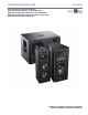


CHAPTER 2: ULTRA XP LOUDSPEAKERS
10
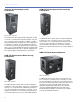
CURRENT DRAW AND CABLE REQUIRE-
MENTS FOR ULTRA XP LOUDSPEAKERS
DC current draw for Ultra XP loudspeakers is dynamic and
fluctuates as operating levels change. Cabling between
Ultra XP loudspeakers and their external power supply adds
resistance and hence causes a voltage a drop at the loud-
speakers. Because lower DC voltages compromise amplifier
performance (peak SPL), and in some cases frequency
response, cable resistance should be kept to a minimum.
Cable Lengths and Cable Gauges
Cable lengths up to 150 feet between the Ultra XP loud-
speakers and their external power supply are supported
with only 1 dB of peak SPL loss using 18 AWG wire. Longer
cable lengths are possible with heavier wire gauges (see
Table 2 and Table 3).
NOTE: The total cable resistance between
Ultra XP loudspeakers and their external power
supply should not exceed 2 ohms.
NOTE: For long cable runs, you can use a large
cable gauge for DC power and a separate bal-
anced audio cable for audio. For more information,
see “Long Cable Runs with Separate Cable for DC
Power and Audio” on page 11.
Calculating the Maximum Cable Length
The maximum cable length for an Ultra XP loudspeaker can
be calculated with the following formula:
maximum length = 2 ohms / 2 * cable resistance
For example, the maximum length of an 18 AWG cable with
a resistance of 0.00636 is 157.2 feet (2 / 2 * 0.00636).
BELDEN 1502 CABLE (OR EQUIVALENT)
The most convenient method of wiring Ultra XP loudspeaker
cables is with a multiconductor cable such as Belden 1502,
which has dedicated conductors for DC power and bal-
anced audio in a single jacket. When wiring loudspeaker
cables with Belden 1502, use the conventions in Table 4.
The red and black wires are 18 AWG, thicker than the other
three wires, and should be used for DC power (cable lengths
up to 150 feet are possible with just 1 dB of peak SPL loss).
The blue, white, and shield drain wires should be used for
audio.
CAUTION: When wiring Ultra XP loudspeaker
cables, it is extremely important that each pin
be wired correctly. Make sure the 48 V DC from the
external power supply is wired directly (and only) to
the 48 V DC pins on the loudspeaker connector, and
that the polarity is observed (negative to negative,
positive to positive) to avoid damage to the loud-
speaker. In addition, make sure that audio pins are
wired correctly; polarity reversals for audio signals
affect system performance.
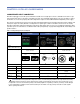
Table 2: Ultra XP Loudspeaker Cable Lengths (AWG)
Cable Gauge Resistance
(/ft)
Approximate
Max. Length
12 AWG 0.0016 600 ft
14 AWG 0.00253 375 ft
16 AWG 0.00402 237 ft
18 AWG 0.00636 150 ft
20 AWG 0.01008 87 ft
Table 3: Ultra XP Loudspeaker Cable Lengths (European)
Cable Gauge Resistance
(/m)
Approximate
Max. Length
2.50 mm
2
0.0052 157 m
1.50 mm
2
0.01076 87 m
1.00 mm
2
0.02087 45 m
0.75 mm
2
0.03307 27 m
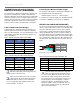
Belden 1502 Composite Cable
Table 4: Ultra XP Loudspeaker Cables with Belden 1502
Wire Signal Gauge
Black 48 V DC power, negative (–) 18 AWG
Red 48 V DC power, positive (+) 18 AWG
Shield drain Balanced audio, shield 24 AWG
Blue Balanced audio, negative (–) 22 AWG
White Balanced audio, positive (+) 22 AWG
Pin #1 48 V DC (–)
Pin #2 48 V DC (+)
Pin #3 Audio shield
Pin #4 Audio (–)
Pin #5 Audio (+)