GB OPERATING MANUAL FOLDING WHEELCHAIR, MODEL 1.736 W e m o v e p e o p l e .
Contents Introduction .................................................................................................. 6 Acceptance .................................................................................................... 7 Adaptation .................................................................................................... 7 Handling the wheelchair ............................................................................. 7 Specifications ..........................................
Height-adjustable leg support ..........................................................................22 Folding up the foot plates ...........................................................................22 Swivelling off and removal of the leg supports .........................................22 Attaching the leg supports ..........................................................................23 Height adjustment of the leg support ........................................................
Wheels ......................................................................................................... 38 Drive wheels .......................................................................................................38 Quick release axle .........................................................................................38 Handrims .............................................................................................................39 Steering wheels .............................
Loading and transportation ...................................................................... 50 Safety information ........................................................................................50 Transport in vehicles .....................................................................................50 Transport security ..........................................................................................50 Transport in handicapped transport automobile .................................
INTRODUCTION We thank you for the confidence you have placed in our company by choosing a wheelchair from this series. This manual is to help you get accustomed to the handling of the wheelchair as well as to prevent accidents. ☞ Note: Please note that the illustrated equipment variants can deviate from your model. The model 1.736, fulfils the wish for mobility and more independence by way of a new styling of the proven MEYRA technology.
ACCEPTANCE All products are checked for faults in the factory and packed in special boxes. ☞ Note: ☞ However, we request that you check the vehicle for possible transport damage immediately on receipt – preferably in the presence of the carrier. ☞ The packaging of the wheelchair should be stored for a further transport that might become necessary. HANDLING THE WHEELCHAIR Specifications The wheelchair, model 1.736 was developed for adults and adolescents.
Use Auxiliary drives Through its constructive advantages the wheelchair can universally be implemented on hard surfaces and therefore an allround-wheelchair: Before attaching auxiliary drives the following notes have to be considered: – for indoors (e.g. apartment, day care), ! – outdoors (e.g. in parks), – as a companion on tours (e.g. in a bus or train). The wheelchair offers manifold adjustment possibilities to individual vital statistics.
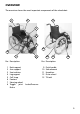
OVERVIEW The overview shows the most important components of the wheelchair. 1 2 9 3 4 5 13 8 7 6 Pos. Description 1 2 3 4 5 6 7 8 Back support Arm support Seat cushion Leg support Calf strap Footrest Steering wheel Toggle joint Brake 12 11 10 Pos.
DRIVING Alignment of the driving behaviour and the personal abilities is to be carried out together with your specialist dealer or therapist and is achieved after a short acquaintance period, test drive. ! Attention: Drive with extreme caution during these first trips! • Observe the section < driving training > in the safety instructions < Mechanical wheelchairs >! Safety information ! Attention: Please follow all instructions in the safety information < Mechanical wheelchairs >.
• Never leave children/adolescents in wheelchairs unsupervised. • Always approach small obstacles, e.g. steps or curbs, slowly and at a right angle (90°) until the steering wheels almost touch the obstacle. Briefly stop the wheelchair and then drive over the obstacle. • Keep well clear of rail grooves, rails and gully covers or similar sources of danger. If not possible, cross such obstacles at a right-angle (90°).
BRAKE By locking the brakes the wheelchair is to secured against unintentional rolling off (parking brake). 1 The locking brake belongs to the most important safety features of a wheelchair and is available as a pressure brake (1). ! Attention: Please observe the maintenance instructions as well as instructions in the section < General safety instructions > and < Brakes > in the safety instructions < Mechanical wheelchairs >.
Pressure Brake A metered braking from driving speed (operating brake) is possible with the brake levers (1) of the pressure brakes. Service brake 1 Press the two brake levers evenly only slightly to the front, this brakes the wheelchair in a metered fashion. Locking the pressure brakes To secure the wheelchair against any unintentional rolling, press both brake levers forward all the way (1). 2 ☞ Note: It should not be possible to push the wheelchair forward when both brakes are locked.
Drum brake for attendant A metered braking from driving speed (operating brake) is possible with the brake levers of the drum brakes. The wheelchair is also to be secured against unintentionally rolling away (parking brake) by engaging these brakes. 1 Locking the drum brakes Pull both brake levers evenly to secure the wheelchair against unintentional rolling away. Press the latch (1) forward. Release the brake lever.
Loosen the drum brakes Pull both brake levers (1) until the latches (2) automatically jump out of the lock. Release both brake levers. – The parking brakes are release and the wheelchair ready to go. ! Attention: For driving the front and rear brake levers must be disengaged. 2 1 ☞ Note: The braking effect depends upon: – the condition of the tyres, – the condition and attachment of the brakes, – the brake lever adjustment, – the road condition.
LEG SUPPORTS !• Attention: Do not use the leg supports to lift or carry the wheelchair. 1 The parking brakes are to be engaged before all assembly work. – This prevents the wheelchair from rolling away accidentally. Calf strap The calf strap (1) prevents the feet from sliding off of the footplates. – It is guided around special ligament (2) and adjusted in length with a velcro fastener. Removal of the calf belt is achieved by opening the velcro straps.
Folding up the footplates The footplates are to be folded up for entry into, exiting the wheelchair or scuttling (forward motion of the wheelchair with the feet) (1). Turning the leg supports to the side For easy transfer out of/into the wheelchair as well as driving closer to a closet, bed or bathtub the leg supports can be swivelled away toward the in-/outside (3) and (4). 1 – Therefore pull or press the respective locking lever (2) and swivel the corresponding leg support inward/ outward.
Removing the leg supports For easy transfer into and out of the wheelchair as well as a reduced wheelchair length (important for transport) the leg support can be removed (1). ☞ Note: Before swivelling the leg support loosen or remove the calf belt on one side. 1 – Remove both feet from the footplates. – Pull or press the locking lever backward (2). – Swivel the leg support sideways and take them off toward the top (1).
Adjusting the height of the footplate Remove the clamping screw (1) to adjust the height. 1 Telescope the foot plate to the desired height and then secure it with the clamping screw. Angle adjustable footplates After loosening the clamping screw (2) pull out the dovetail connection and adjust the angle of the footplates. ☞ The setting screw (3) serves to horizontally correct the angle of the footplates. Afterwards retighten the clamping screw.
Continuous leg support The footboard of the continuous leg support (1) can be folded up to the side. Folding up the foot board For an unobstructed foot area, fold up the left side of the foot board to the right as far as it will go (2). 1 Folding down the foot board Fold down the left side of the foot board until it rests on the foot board holder (3). Height adjustment of the footboard 2 Loosen the clamping screw (4) to adjust the height.
Adjusting the height of the footboard 1 Loosen the clamping screw (1) to adjust the height. Telescope the footboard to the desired height and then retighten the screw. Angle adjustable footboards After loosening the clamping screw (2) pull out the dovetail connection and adjust the angle of the footplates. Afterwards retighten the clamping screw.
Height-adjustable leg support Folding up the footplates For entry and exiting the footplates (1) are to be folded up and the calf cushions (2) swivelled outward in driving direction. 2 1 Swivelling off and removal of the leg supports For easy transfer out of/into the wheelchair as well as driving closer to a closet, bed or bathtub the leg supports can be swivelled outward and removed. 3 ☞ Note: ☞ Operate parking brakes. – This prevents accidental rolling of the wheelchair (see section < Brakes >).
Attaching the leg supports With the leg support in a swivelledaside position, hang it in and then swivel it to the front until the locking device audibly latches. ☞ Note: After swivelling the leg support inward again do not forget to check the corresponding locking device. 1 – Afterwards swivel the calf cushion inward again. Height adjustment of the leg support When seated in the wheelchair, ask a carer to raise the leg support to the desired level.
Adjusting the height of the footplate Loosen the clamping screw (1) to adjust the height. ☞ Note: ☞ Loosen the clamping screw (1) so 1 far that no damage to the coating occurs during the adjustment. ☞ Observe the maximum extension mark (2). Telescope the foot plate to the desired height and then retighten the clamping screw (1). Depth adjustment of the calf cushion Depth adjustment of the calf plates is achieved after removing the respective screws (3).
ARM SUPPORTS !• Attention: Do not use the arm supports to lift or carry the wheelchair. 1 Do not drive without the arm supports! • If possible propel the wheelchair over the handrims. – Danger of jamming between drive wheel and arm support! • When being pushed by the attendant the user has to keep his hands on the arm supports or in his lap and not at the sides between body and arm support.
Inserting the arm support To attach the arm support insert the bolt currently in the slanted position (1) into the respective receptacle (2). 3 1 ☞ When swivelling down the arm 2 support, take care that the bracket (3) grips around the back tube. – Swivel the arm support forward into the corresponding receptacle until the locking button (4) audibly engages. 4 ☞ Note: The swivelling forward automatically engages the rear locking device of the arm support.
CLOTHES GUARD X 4 The distance (X) to the clothes guard running parallel to the wheel diameter (1) is to be aligned to the selected wheel position. ! Attention: The distance X between the driving wheel and the mudguard should be as small as possible (approx. 1 cm). – Danger of crushing! Adapting the clothes guard – Remove the corresponding drive wheel. ☞ Hereto observe chapter < Drive wheels >. 2 – Dismantle the screwed connections (2).
SEAT Seat strap, standard 1 The seat strap (1) is tensed through the seat tubes and can be bent upward in the middle for folding (2). ☞ Therefore observe chapter < Folding/Unfolding >.
Seat cushion The seat cushion is aligned to the centre and placed from front to back onto the velcro straps at the sides of the adjustable seat strap (1). The seat cushion can be removed toward the top for folding (2). – Velcro fastener. 1 Adjusting the seat depth The seat depth can be continuously adjusted by max. 3 cm by sliding the front adjustable seat strap (3). ☞ Note: For this slide the two velcro seat straps parallel on both sides.
BACK SUPPORT Back support belt, standard The back strap is tightened through the back tubes (1). The extended back support element is velcro strapped underneath the seat strap. 1 Adjusting the back support belt Two holes each are already in the back tubes t attach the back strap (2). 1. Screw out the attachment screw (3) on each side. 2. Adjust the back support strap in height. 3. Screw the attachment screw (3) on each side through the back support strap into the back tube and tighten (2).
Angle adjustable back support The angle adjustable back support (1) can be adjusted in angle by +/- 10° in 5°-steps. Adjustment of the back support angle – Therefor remove the arm supports (2). 1 ☞ Observe chapter < Arm support >. – Then screw out the attachment screws (3) on both sides (2). 3 – Then adjust the back support tubes parallel to the desired back angle. – Then remount the screws on both sides (3) and adjust the back tube brackets on both sides.
Height adjustable back support The height adjustable back support (1) is continuously adjustable in height (2). Adjusting height the back support – Therefor remove the back cushion (3). – Velcro fastener. 1 ☞ Observe chapter < Adjustable back support >. – Then loosen the clamping screws (4) on both sides and adjust the back tubes parallel according to the cm scale at the side to the same height (5). – Then retighten the attachment screws (4) on both sides.
Adjustable back The adjustable back is adjustable through a velcro strap, the so called spanning straps (1). The cushion (2) is placed over it and attached with the velcro strap. 1 2 Adjusting the adjustable back ☞ Note: ☞ The fitting of the adjustable back (1) is best carried out with the user sitting in the wheelchair and the seat angle is set at 0°. ☞ Adjustment is carried out from the bottom to the top.
Place the back cushion The back cushion (1) is to be folded over in the centre between the two horizontal seams 180° around the upper spanning straps (2), (3). – This creates a soft upper edge. 1 2 ☞ Note: When the user leans against the front cushion again, pay attention that: 3 ☞ The pressure of the back must be spread evenly throughout the back cushion. ☞ A complete hand should fit in between the cushion and back at the upper edge of the back cushion.
PUSH HANDLES Height adjustable push handles The height adjustable push handles (1) are attached to the back support with a clamping jig each (2) and can be adjusted to the requirements of the attendant. 1 The push handles are continuously height adjustable, swivelling in steps of 30° and secured against being pulled out. ☞ Note: Further varieties of push handles are optionally available at you specialist dealer.
Removing the push handles Loosen the clamping screw with the clamping lever (3) and pull the according push handle up as far as it will go. Press the respective spring button (1) inward and pull the push handle out of the clamping device (2). Inserting the push handles Press down the spring button (1) and insert the push handle from the top into the respective clamping device (2).
Push handles with tube guidance The push handles (1) are guided swivel-proof inside the back tube and steplessly height by up to 10 cm. 2 Height adjustment – First hold onto the push handle that is to be adjusted then swivel the corresponding clamping lever (2) with the other hand into the horizontal position. 1 – Then adjust the push handle to the desired height and clamp it tight (3). – For this swivel the clamping lever downward (1).
WHEELS Drive wheels The drive wheels are on a quick release axle. ☞ No person may be seated in the 1 wheelchair during assembly or removal. The wheelchair must stand on a level and firm surface. Before starting the disassembly work, support the frame to prevent the wheelchair from tipping over and secure it to prevent an unwanted movement or tipping over. Quick release axle The driving wheels can be removed and reassembled without any tools.
Handrims All handrims are designed for a 15 mm to 25 mm (standard adjustment) (1) distance to the drive wheel. ! • Attention: Replacement of handrims or modification of handrim distances should always be carried out by your specialist workshop. 1 Observe the safety instructions < Mechanical wheelchairs >, chapter < Handrims >! Steering wheels The steering wheels can be exchanged without difficulty. For removal of the wheels the screw axle (2) has to be disassembled.
SUPPORT WHEELS The support castors serve to increase the tilting stability. ! Attention: In certain situation the support castors do not provide sufficient protection against falling over. 1 1 Therefore, do not: ▲ Leaning the upper body far back. ▲ When the wheelchair starts suddenly, especially when driving uphill. ▲ Driving over steps, e.g. curbs or stairs. – Danger of falling over forwards.
Stick-in support wheels Removing/attaching the support castor To remove / insert the support castors press down the respective spring button (1). 1 When replacing the support castors slide them in until the spring button (1) automatically snaps into place. 2 ☞ Note: The spring button must engage visibly and audibly.
MANOEUVRE ROLLERS For driving through tight passages (e.g. in trains) the wheelchair can be pushed over the shunting castors (1) without drive wheels by an attendant. By removing the drive wheels the wheelchair can be used as a transit chair when combined with the shunting castors.
SEAT BELT 3 The seatbelt serves to strap in a person sitting in the wheelchair. 2 – Additional stabilisation of the sitting position. – Prevents the user from falling forwards out of the wheelchair. 4 – Continuous adjustment to suit the user’s needs. The seatbelt is screwed from the back onto the respective back support tube.
THERAPY TABLE ! • Attention: Place, adjust and reposition or remove the therapy table only after activating the brakes. Sharp objects (e.g. watches, rings, knives or belt buckles) as well as coarse dust can cause unattractive brush marks in the surface of the therapy table.
INDIVIDUAL ADJUSTMENT 2 The adjustment possibility offers a: 1 – individual adaptation of the seat height to your lower leg length, – user compatible seat angle, – increased tilting stability. ! • Attention: Individual adjustments like repositioning the drive and steering wheels are only to be carried out by your specialist dealer. Every new adaptation can change the driving behaviour.
Driving wheel position The positions of the drive wheel depends on: 2 – the desired seat height, 1 – the seat angle, – the steering wheel. ! Attention: If the vario-block (2) with the axle receptacle (1) is repositioned horizontally, the wheel base is changed and thus also the driving behaviour.
Back support belt height The back strap height can be adjusted into a further attachment position by repositioning the back strap (1). – Therefore first remove the attachment screws (2) of the back strap. 1 – Afterwards reposition the back strap and retighten with the attachment screws (2).
FOLDING/TRANSPORT Folding/Unfolding Folding the wheelchair The Lightweight Wheelchair can be folded without tools in few steps, (1). Remove the seat cushion, if applicable. If necessary remove the calf strap. Remove the leg supports or fold up both footplates, see section < Leg supports >. If available separate the back stiffening bracket, therefore view chapter < Back stiffening bracket >. Pull the back support extension off toward the bottom, view chapter < Back support belt >.
Carrying the wheelchair Your wheelchair can be carried without difficulty when folded. Fold the wheelchair, therefore view chapter < Folding the wheelchair >. From the front push one lower arm under the upward folded seat belt. Place other hand underneath the rear seat fold for support. 2 Lift the wheelchair to horizontal position. Unfolding the wheelchair Tip the wheelchair slightly to one side in order to make the unfolding easier.
LOADING AND TRANSPORTATION Safety information ▲ For the transport in vehicles, you must leave the wheelchair and sit in a suitable seat in the vehicle. The transportation of persons in wheelchairs is prohibited. – The wheelchair is not designed to withstand the forces which are generated in accidents, which exposes the user to considerable risks. Transport in vehicles Transport security Carry out the following steps when the wheelchair is located in the transport vehicle: – Operate parking brakes.
Transport in handicapped transport automobile Should transport in an electric vehicle be inevitable, it must feature a retaining system according to DIN 75078 part 2. Should you require a retaining system please contact a specialist dealer. The transport vehicle (handicapped transport vehicle) needs to have the equipment for transporting wheelchairs according to DIN 75078 Part 1. This norm describes a „power-knotsystem“.
Product liability instructions ☞ Transport in the wheelchair with a handicapped transport automobile (BTW) is done at own risk! ☞ We do not accept liability for dam- Special safety instructions for shell seats ! ages or other possessions that occurred through the transport in a handicapped transport automobile.
SERVICE Plastic parts Cleaning and maintenance The arm supports and parts are made of high-quality plastic. ☞ Note: ☞ Do not clean the wheelchair with a ☞ Only clean the plastic parts with warm water and neutral detergent or soft soap. high-pressure cleaner! ☞ For care you should use silicon free cleansing or care agents on a warm water basis such as the leather care emulsion from Sonax. – In doing so the manufacturers instructions are to be observed. ☞ Do not use aggressive cleaning agents e.g.
Chassis Reinstallment The chassis and wheels can be cleaned damp with a mild detergent. Afterwards dry off well. Before reimplementation the wheelchair is to undergo a complete inspection. ☞ Note: ☞ Note: Check the chassis for corrosion damages as well as other damages. Occasional application of a light cover of oil to all moving parts (see also Maintenance Instructions) will ensure that your wheelchair will give you many years of service.
Maintenance instructions WHEN WHAT Remark Before starting out Test brakes for faultless operation Carry out test yourself or with a helper. Activate brake lever to the limit. The locked wheels should not be able to turn under operating conditions. If they can still turn, the brakes must be repaired by a specialist workshop. Check brake for wear Move brake lever to the side Carry out tests yourself or have a helper do it.
Maintenance instructions WHEN WHAT Remark Before starting out Check air pressure of the tyres Do it yourself or with the aid of a helper. Use a tyre pressure tester or, if not available, the 'thumb press' method or similar (view Safety instructions < Mechanical wheelchairs > chapter < Brakes >). Standard tyres: 4 bar = 56 psi High-pressure tyres: 8.0 bar = 116 psi 56 Check tyre profile Carry out visual check yourself.
Maintenance instructions WHEN WHAT Remark Every 8 weeks (depending on distance covered) Lubricate the following components with a few drops of oil Do it yourself or with the aid of a helper. Components must be free from used oil residues before lubrication. Please ensure that excess oil does not contaminate the environment (e.g. your clothing) – Moving parts of the locking mechanism. – Brake lever bearings.
Flat tyre If a flat tyre occurs to the air filled tyres due to puncture by sharp objects such as nails, screws, glass splinters, etc. the damage should be eliminated by repairing (mending the inner tube) or replacing the inner tube. ! Attention: Sitting in the wheelchair during a wheel change is not permitted. The wheelchair must stand on a level and firm surface.
Adjusting the brakes According to the < Maintenance instructions > the brakes are to be checked for function after each repositioning of the drive wheels and readjusted if necessary. – Loosen the clamping screws (1) of one pressure brake. 1 – Afterwards Preadjust the respective brake by repositioning it accordingly. Pressure brake: – For this slide the brake bolt of the inactivated brake (2) to approx. 5 mm - 10 mm in front of the drive wheel and align it at a right angle to the drive wheel.
Repair To conduct repair or maintenance work trustfully contact a specialist workshop. It is briefed in carrying out the work and has educated personnel. Customer Service Please contact a specialist dealer if you have any questions or need help. A specialist dealer has been trained by us in our factory according to our guidelines and can give advice and carry out maintenance, servicing and repairs. Spare parts Spare parts can only be ordered from specialist dealers.
INSPECTION For safety reasons and to prevent accidents which can result from wear not detected in good time, an annual inspection is necessary in the case of normal operating conditions. This is to be carried out in accordance with the following service checklist. Have this work carried out by a specialist workshop in order to ensure that the wheelchair offers the highest level of safety and reliability. The employees of the workshop are familiar with the technology of the vehicle and have suitable tools.
List of annual maintenance work Preparation for visual check Remove the seat and back support elements, leg supports, arm support units. If necessary, clean the vehicle or the modules before the visual check. Visual check ❑ Check frame, attachments and accessories for damages, corrosion as well as damages to the coating. General checks ❑ Check the securing screws for tightness. ❑ Check the securing of all add-on elements.
Inspection certificate through the dealer Vehicle data: Model: Delivery note no.: Vehicle identification No.
Recommended safety inspection (at least every 12 months) Recommended safety inspection (at least every 12 months) Stamp of specialist dealer: Stamp of specialist dealer: Signature: Signature: Place, date: Place, date: Next safety inspection in 12 months Next safety inspection in 12 months Date: Date: Recommended safety inspection (at least every 12 months) Recommended safety inspection (at least every 12 months) Stamp of specialist dealer: Stamp of specialist dealer: Signature: Signature:
TECHNICAL DATA All data within the following table relates to the standard version of the stated model. Dimensional tolerance is +/-1.5 cm, +/-2° Short form of wheelchair dimensions: SH = Seat height SW = Seat width SD = Seat depth BH = Backrest height Model:..................................................................................................... 1.736 Type plate: ..............................................................................
Seat width Short frame: ............................................................................................. 32 to 36 cm Medium frame: ........................................................................................ 38 to 50 cm Long frame: .............................................................................................. 48 to 58 cm Seat strap depth Short frame: .............................................................................................
Transport dimensions: Length (without drive wheels, without leg supports) Short frame: .......................................................................................................49 cm Medium frame: ..................................................................................................61 cm Long frame: ........................................................................................................69 cm Width (folded wheelchair):..................................................
(Short frame) Max. permissible total weight *: ...................................................................... 90 kg Max. permissible user weight (including additional load): ............................ 75 kg maximum additional load:................................................................................ 10 kg Empty weight: ............................................................................................ min. 12 kg (with drive wheels) (Medium frame) Max.
Tools The following tools are required for adjustments and maintenance: Open-end or ring spanner .............................. Wrench width (WW) 8 / 10 / 13 mm Hexagonal stud wrench ............................................ Wrench width 3 / 4 / 5 / 6 mm Phillips screwdriver .............................................................. Size PH resp. PZ 0 / 1 / 2 Slot screw drivers ........................................................................................
Meaning of the labels on the wheelchair Attention! Read the operating manuals and other provided documentation. Do not lift the wheelchair at the arm supports or leg supports. Detachable parts are not suitable for carrying. Attention Readjust the brakes. Attention Increased danger of tilting when on inclinations / slopes, especially in combination with short wheel base.
NOTES 71
NOTES 72
NOTES 73
GUARANTEE We accept a guaranty for this product according to the legal regulations. Apart from this we warrant: – 2 years for frame. We reserve the right to make technical improvements. In the case that you find fault in this product or parts thereof, return the following guaranty slip under statement of the reasons for your complaint. Do not forget to include the requested information regarding model description, delivery note number with date of delivery, vehicle identification number (Fz-I-Nr.
GUARANTEE COUPON Fill in the details! If necessary, copy and return. Guarantee Model designation: Delivery note no.: Vehicle ID No. (Fz-I-Nr.
Your specialist dealer: We 76 move peopl e. MEYRA-ORTOPEDIA Vertriebsgesellschaft mbH Meyra-Ring 2 · D-32689 Kalletal-Kalldorf P.O. Box 1 703 • D-32591 Vlotho Fon +49 (0)5733 922-355 Fax +49 (0)5733 922-9355 info@meyra-ortopedia.de www.meyra-ortopedia.