en Scooter Model 2.364 Operating manual W e m o v e p e o p l e .
Contents Introduction................................................................................................... 5 Indications...................................................................................................... 6 Acceptance..................................................................................................... 6 Specifications................................................................................................. 6 Use..........................................
Driving speed.......................................................................................................21 Forward driving speed...................................................................................21 Backwards driving speed...............................................................................21 Left/right turns....................................................................................................22 Brakes........................................................
Retaining strap....................................................................................................39 Fastening the retaining strap........................................................................39 Opening the retaining strap.........................................................................39 Adjustment of belt length............................................................................39 Maintenance........................................................................
INTRODUCTION We thank you for the confidence you have placed in our company by way of choosing the SCOOTER. The model you selected fulfils your desire for mobility and more independence. As any other vehicle, the SCOOTER is a technical aid. It is subject to explanations, requires regular care and can cause danger when used improperly. The correct handling must therefore be learned. This operating manual is to help you get accustomed to the handling of your SCOOTER as well as to prevent accidents.
INDICATIONS ACCEPTANCE If the following indications occur we recommend the application of this mobility product: All products are checked for faults in the factory and packed in special boxes. ☞ Extremely limited walking abilities ☞ Note: in the scope of the basic requirement to move around in your own apartment and to be able to leave the apartment, in order to catch some fresh air outside or in order to reach places close by for daily demands.
USE ! Attention: The general capability of the driver to participate in traffic must be given! This model is a SCOOTER for driving on firm, level surfaces outside and open indoor spaces (e. g. shopping centres). 1 It serves exclusively for the conveyance of a sitting person. Other pulling or transporting uses do not comply with its intended purpose. This model is a SCOOTER, mainly for outdoor use on firm, level surfaces.
ADJUSTMENT LIFE SPAN The specialist dealer hands your SCOOTER over under consideration of all relevant safety regulations in an operationally ready state and adjusted to your demands. We expect an average lifespan of about 5 years for this product, as far as the product is applied for its designated purpose and all maintenance and service guidelines. ☞ Note: ☞ We recommend a regular check The life span of your product depends upon the frequency of use, the application environment and care.
OVERVIEW Model:2.364 4-wheel The overview shows the most important components and operating equipment. 1 2 3 9 10 11 4 12 5 6 8 Pos. Description 1 2 3 4 5 6 7 8 Seat Handle bar grip Steering column Drive key Headlight Front indicator Steering wheel Drive wheel 7 13 16 15 14 Pos.
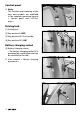
Control panel ☞ Note: The function and meaning of the keys and symbols are explained in the separate operating manual < Control panel with LCD-Display >. 1 Driving lock (1) Driving lock (2) Key position 0 (OFF) 2 3 (3) Key position 45° (Push mode) (4) Key position 90° (ON) Battery charging socket (5) Battery charging socket – The battery charging socket (5) is protected by a cover plate that can be swivelled to the side. ☞ View chapter < Battery charging procedure >.
HANDLING THE SCOOTER ! Attention: Observe the safety and general handling instructions < Electronic vehicles >! 1 Supplementary safety information ☞ Note: Do not grab with fingers into open frame tubes (e. g. after loosing cover plugs or caps). – Danger of injury! ! • Attention: A stable sitting position is to kept while using the SCOOTER, even when not in motion and especially on hills and slopes.
Drive key Position of drive key ☞ Therefore also observe the oper- 1 ating manual SCOOTER < Control panel with LCD-display >! Position OFF The driving key is inserted parallel to the steering column as far as possible into the driving key socket (1). – For switching off turn the driving key from the position (2)+(3) as far as possible counter clockwise (1). 2 ☞ The SCOOTER is switched off. Position push mode The driving is inserted turned clockwise by 45° inside the driving key socket (2).
Director The desired driving speed is achieved through activation of the director via the: – the actuator as a seesaw device for thumb activation (standard), – the actuator as a thumb or finger seesaw lever (option) (1), 1 – acceleration rotary grip (option) (2), – foot accelerator (option) (3).
Drive-/push mode ☞ Note: 1 Switch the SCOOTER into the push mode only for manoeuvring on a level surface. ☞ The weight of the SCOOTER makes corresponding steering and pushing forces necessary. Selecting the motor mode In order to establish drive mode turn the driving key to position ON (1). 2 ☞ Therefore observe chapter < Driving key >. ☞ The SCOOTER is now ready for use. Selecting the push mode In order to establish push mode turn the driving key to position Push (2).
Emergency lock down of the magnetic brake The magnetic brake on the motor is automatically activated when battery voltage is lost. 2 ☞ The SCOOTER is thus secured completely against rolling away. Disconnecting the emergency lock 1 In order to disconnect the emergency lock for pushing the SCOOTER the activated magnetic brake can be released at the motor [1]. 1. Before disconnecting the emergency lock switch the SCOOTER off. ☞ Therefore observe chapter < Driving key >. 2.
Selecting the operation In order to obtain operational readiness of the SCOOTER the following directions are to be carried out in the indicated order. ☞ Note: Before first use the drive batteries should be charged through the charging socket (1). ☞ Therefore observe chapter < Battery charging procedure >. ! Attention: Only enter or exit the seat of the SCOOTER when the driving key is pulled.
2. Adjusting the steering column The steering column is to be adjusted so that the SCOOTER can be steered comfortably and safely. – For adjusting the steering column press the lever of the steering column locking device (1) down. ☞ Hereto observe chapter < Steering 1 column >. 3. Switching on the SCOOTER Turn the driving key into the ON position (2) in order to switch the Scooter on (3). 2 ☞ Therefore observe chapter < Driving key >.
PRE-OPERATION CHECKS ☞ Therefore observe the operating manual < Control panel with LCDdisplay >! Before starting to drive, the following should be checked: ☞ The status of the battery charge through the battery gauge (1), – Therefore observe < Battery gauge >. chapter ☞ the pre-selected maximum final speed setting (2). – Therefore observe chapter < Limiting the maximum speed >. ☞ conduct a functionality test. – For this start driving slowly.
Battery charging procedure For the battery charging procedure park and secure the SCOOTER on a level surface. ☞ View chapter < Securing the SCOOTER >. 1. Swivel the cover of the battery charging socket to the side and plug the battery charger into the battery charging socket (1). 1 Attention: Do not insert anything other than the battery charging plug into the battery charging socket. – Danger of short circuit! ☞ Therefore also observe the operating manual of the battery charger. ! 2.
DRIVING BEHAVIOUR Speed is determined by motion of the director: 2 – The accelerator lever (1), – the acceleration rotary grip, – the foot accelerator as well as the pre-selected final speed. ! Attention: Drive especially carefully during the first journeys! ☞ Pre-select the lowest final speed for this purpose. ☞ Therefore also observe the operating manual < Control panel with LCD-display >! Direction of travel ☞ Note: ☞ The speed is reduced automatically during the rearward travel.
Accelerator lever The driving direction is determined through the activation side of the accelerator lever. 2 Forward motion [1] Right Press cap with thumb dent [2] Left Pull lever with hand (option) 3 1 2 4 Rearward travel [3] Left Press cap with thumb dent [4] Right Pull lever with hand (option) Driving speed Slowly move the director out of the basic position until the desired driving speed is reached. Forward driving speed Move the right lever side [1] of the driving director forward.
Left/right turns In order to drive curves, move the steering column to the right or left with the handles, depending on the desired curve radius. ☞ Curves are to be driven through at ! adequate speed. Attention: Danger of tilting when turning around, especially on slopes and hills! The SCOOTER features and automatic blinker reset after driving through a curve. ☞ The additional turn-signal control is mandatory in all cases! ☞ Note on speed reduction: ☞ The SCOOTER features a three step speed reduction.
BRAKES ! Attention: If the braking force reduces immediately have the brakes repaired by a specialist workshop. ☞ Observe the safety and general Emergency braking Let the driving lever (director) independently jump back into the zeroposition. ☞ The SCOOTER brakes down at shortest distance.
LOADING AND TRANSPORTATION ☞ Do not use the back support, arm supports or steering column in order to lift the SCOOTER! ! Attention: Secure the SCOOTER before lifting! ☞ Therefore observe chapter < Securing the SCOOTER >. Loading The SCOOTER can be loaded with the aid of ramps or lifting platforms. ☞ Note: Observe safety and general handling instructions < Electronic vehicles > chapter < Ramps and lifting platforms >.
Transport security ☞ View document safety and general handling instructions < Electronic vehicles > chapter < Transport in motor vehicles or conveyors >. – Establish electrical safety ☞ For this observe the regulations of the respective transport company. 1 – Locking the SCOOTER ☞ Therefore also observe chapter < Securing the SCOOTER >. ☞ The selection lever drive/push mode is in drive mode position. ☞ Dismantled parts of the SCOOTER are to be stored safely and protected.
Reducing the size of the SCOOTER For storage or the transport (e.g. in a car), the size of the SCOOTER can be reduced as follows (1). 1. Lock the SCOOTER. ☞ Therefore observe chapter < Securing the SCOOTER >. 2. Remove the front basket. ☞ Therefore observe chapter < Front basket >. 3. Remove the seat. ☞ Therefore observe < Seat >. chapter 4. Swivel down the steering column. ☞ Therefore observe chapter < Steering column >.
Disassembling the SCOOTER into components 3 The SCOOTER can also be disassembled into several components as follows for the transport in a small vehicle. ➀ Front basket ☞ Therefore observe 5 6 2 chapter 4 1 < Front basket >. ➁ Seat ☞ Therefore observe chapter < Seat >. ➂ Rear panel ☞ Therefore observe chapter < Removing the batteries >. ➃ Batteries ☞ Therefore observe chapter < Removing the batteries >. ➄ Rear section ☞ Therefore observe chapter < Removing the rear panel >.
Removing the batteries 1. Switch off the SCOOTER and pull out the drive key. 2. Remove the seat [1]. ☞ Therefore observe < Seat >. chapter 3. The ball grip of the selection lever has to be screwed off before removing the battery cover (2). ☞ In order to prevent loosing the ball grip it should be replaced after the battery cover has been removed. 1 2 4. First lift of the rear panel (3) then store it in a protected and safe spot.
6. Open the velcro fastener of the spanning belts of each battery (1). 7. Lift out the batteries (2). Removing the rear revetment 1. Unplug the connections (3) of the back lights. ☞ To pull them off hold onto the connection plugs. – Do not pull on the cables! 1 ☞ Note: The plug is secured by a spring lock that has to be unlocked by pressing it together at the upper end. 2. Pull the main plug for the controller (4). ☞ Previously remove the screws at the side.
3. Pull out the locking lever (1) first, then swivel the now unlocked rear chassis from the front part and place it onto the floor (2). 1 ☞ Note: For easier unlocking first slightly lift the seat tube (3) the fold the rear chassis (4) toward the back. Afterwards press the front chassis over the seat tube (3) slightly down and place it on the floor (2). 4 Folding down the steering column 1.
Reassembly of SCOOTER-components 1 ☞ Before assembly a visual check of the single components should be conducted for completeness and damages. ☞ Here the following is to be observed closely: – The brackets to receive the drive may not be bent. – The locking bolt to connect the front and rear chassis is at the end of the safety wire. – The connection cables are not damaged. 2 Inserting the rear chassis First put the drive into drive mode. 1.
3. Replace the locking bolt (1). ! Attention: The locking bolt has to be visibly pushed through. 4. Replace the main plug (2). ☞ Replace the screws at the side of the main plug to the for safety. 1 5. Re-establish the plugged connection of the tail lights (3). ☞ The plug must catch when being established. – Conduct a slight pulling test on the plug. Raising the steering column 2 3 1. Activate the locking lever (4) to raise the steering column.
Mounting the batteries Mounting is done in reverse order. 1. Set the batteries into the frame and secure them with the spanning straps (1). ! Attention: Make sure that the cables are correctly routed when mounting the batteries. – Danger of cable damage. 1 2. Reconnect the battery cable (2) on both sides. ☞ Insert the plugs as far as possible. – Conduct a slight pulling test on the plug. 2 3. Replace the battery lid (3). ☞ If necessary screw the ball grip off of the selection lever first. 3.
COMPONENTS Seat ☞ Note: The seat supplied (1) may vary from the one shown in the illustration. The seat (1) can be removed and is height adjustable. 1 Turning the seat The seat can be turned for an easier transfer to or from the seat [2]. In order to disengage the seat locking device, press the lever at the side (3) upward. ! Attention: Do not reach between the seat lever with the fingers while doing so.
Removing the seat In order to remove the seat [1] press the lever at the side (2) upward ! • Attention: Grab sideways under the seat surface in order to lift the seat. Do not reach between the seat lever with the fingers while doing so. ☞ Danger of squashing the fingers! 1 Attaching the seat In order to insert the seat [3] press the lever at the side (2) upward ! • Attention: Grab sideways under the seat surface in order to lift the seat.
Arm support ! Attention: Do not lift or carry the seat using the arm supports. Swivelling up the arm support The arm supports can be swivelled up for an easier transfer to/from the seat [1]. Adjusting the height of the arm supports 1 2 The height of the arm supports can be steplessly adjusted after loosening the respective clamping screw (2). ☞ Maximally lift the arm supports upward up to the marker. ☞ After the height adjustment retighten the clamping screw (2).
Back support The back support can be folded down onto the seat surface (1). To raise the back support swivel it upward toward the back (2). Adjusting the headrest height After activating the locking spring (3) the height of the head support can be adjusted. 1 ☞ After adjusting the height of the head support release the locking spring (3) and let the head support engage into the next possible position by sliding it up or down. ☞ Note: Check the locking device.
Front basket 2 The front basket can be lifted off upwards (1). For attachment the front basket is placed onto the two brackets (2)(3). Support castors The support castors (4) increase the stability against tipping over to the rear when crossing an obstacle or driving on a rising gradient. ! 1 Attention: Support castors do not provide sufficient protection against tipping over in certain situations.
Retaining strap 4 The retaining strap [1] serves to hold a person sitting inside the SCOOTER in place. 2 3 – Additional stabilisation of the sitting position. – Prevents the user from slipping forwards out of the seat (e.g. during abrupt braking). The retaining strap is screwed onto the bottom of the seat.
MAINTENANCE An incorrect or neglected cleaning and maintenance results in a limitation of the product liability. Maintenance The following maintenance schedule gives you a guide for carrying out the maintenance. ☞ They do not give information about the actual extent of work required on the vehicle.
Maintenance schedule WHEN WHAT REMARK Before starting out General Carry out test yourself or with a helper. Test for faultless operation. Checking the magnetic brake Carry out test yourself or with a helper. Switch the selection lever drive- / push mode to drive mode. If the SCOOTER can be pushed, have the brakes repaired immediately by the specialist workshop. – Danger of accidents! Especially before driving in the dark Lighting Carry out test yourself or with a helper.
WHEN WHAT REMARK Every 6-8 weeks (depending on distance covered) Wheel attachments Do it yourself or with the aid of a helper. Wheel nuts or screws are to be checked for tight fit. Securely tighten any loosened wheel nuts or screws and retighten again after 10 operating hours or resp. 50 km. Contact specialist workshop upon demand.
Tyre damage on pneumatic tyres ☞ For repairing tyre damage we recommend the use of a foam cartridge that is available in speciality shops. – Afterwards look up a specialist workshop as soon as possible.
Lighting 1 ☞ Note: If a turn-signal bulb is defective, the remaining one blinks at double frequency. Replacing bulbs defective filament Switch off the SCOOTER before replacing a defective bulb. ☞ Note: ☞ Have a defective bulb in the front replaced in a specialist workshop. ☞ Hold onto the new bulb with a dry cloth. Adjusting the headlights The housing of the light (1) must be adjusted so that the light cone is visible on the driving surface.
Indicator light/front Spherical bulb: 12 V / P21W BA 15s 1 Removal: – Switch off the SCOOTER. – Remove the turn signal with the defective bulb from the front revetment (2). – Therefor loosen the attachment nut (1). – Remove the dispersion disc with a slot screw driver (2). – Press the defective bulb (4) slightly into the socket against the spring, turn clockwise (bayonet-catch) and pull it out of the lamp socket. Mounting: 2 – Insert a new spherical bulb.
Rear light The rear and indicator lights (1) are equipped with long living LED-technology. ☞ Note: In case of a failure we recommend to contact a specialist workshop.
Fuses/connections Mains-/battery fuses The main-/battery fuses are located above the batteries in a fuse holder (1). Charging and control fuse 1 The charging and control fuse is located on the left behind the drive in a fuse clamp (2). Replace fuse ☞ Note: Have a defective fuse replaced by a specialist workshop. – Separate the plugs of the electrical connections. 2 ☞ Note: The plugged connections are secured by spring locks that have to be unlocked by pressing the upper ends together.
FAULT CORRECTION Fault Cause Remedy The display shows nothing after activation. A main-/battery fuse is defect. Insert a new charging fuse or have it repaired in a specialist workshop. Batteries deep discharged Have it repaired by the specialist workshop. The accelerator lever moved too early. Switch the SCOOTER off and on again if this happens. The selection lever drive-/push mode is set to push mode.
Information for the specialist dealer Programming the driving behaviour A maintenance and service manual is available upon demand, in which you can for example find the following information: ☞ Therefore observe the respective The driving behaviour of the SCOOTER can be adjusted through the programming device. < Maintenance and service manual >. 1. Adjustments that can be carried out with tools. 2. Step by step explanations to important repairs. 3. Information on model specific amendments. 2.
TECHNICAL DATA The kilometric performance is greatly reduced by: Kilometric performance – frequent uphill driving, Kilometric performance depends to a large extent on the following factors: – poor drive battery charge condition. – battery condition, – low ambient temperature (e.g. in winter), – weight of the driver, – driving speed, – frequent starting and stopping (e.g.
Fuses ☞ Therefore observe chapter < Fuses/connections >. Mains-/battery fuse:............................................................. 2 x 80 A Charging/control system fuse:................................................... 10 A Lighting Headlight bulb:............................. Filament bulb 12 V / 15 W P26S Front indicator:................................Filament bulb 12V/10W BA15s Tools The following tools are required to replace a turn signal bulb: Phillips screwdriver.......................
Model 2.364 All data within the following table relates to the standard version of the stated model. Dimensional tolerance ± 1.5 cm, ± 2°. Model:.....................................................................................2.364 (4-wheel) Type plate:........................................................................................ at the seat brace Class of use as per DIN EN 12184......................................................................Class C Life span:............................
Climatic data: Ambient temperature:..................................................................... -25 °C to +50 °C Storage temperature:........................................................................ -25 °C to +65 °C Batteries: Battery dimensions (L x W x H):................................................ max. 21 x 17 x 18 cm Sealed drive batteries:..................................... 2 x 12 V 42,5 Ah – 5 h / 50 Ah – 20 h Range (see Kilometric performance): 50 Ah (20 h) with 6 km/h:........
Performance - mechanical in case of increased user weight from 130 kg to 150 kg: The values are not within the norm EN 12184. Technical hill-climbing ability with max. 150 kg user weight:..............[10° (18 %)] max. permissible rising gradient:...........................................................[8.5° (15 %)] max. permissible falling gradient:..........................................................[8.5° (15 %)] max. permissible transverse gradient:.................................................
Meaning of the labels on the SCOOTER Attention! Read the operating manuals and other provided documentation. Do not lift the SCOOTER at the arm supports or leg supports. Removable parts are not suitable for carrying. Drive mode Push mode Push only on level surfaces. Indication for charging socket Attachment possibility of the transport securing system. Symbols The arrow with the hand shows suitable areas to hold on to.
Meaning of the symbols on the type plate Manufacturer Order number Serial number Production date (Year – Calendar week) Permitted user weight Permitted total weight Permitted axle loads Permissible rising gradient Permissible falling gradient Permitted final speed The product is licensed as a seat inside a handicapped transport vehicle (HTV). X 56 The product is not licensed as a seat inside a handicapped transport vehicle (HTV).
INSPECTION CERTIFICATE Vehicle data: Recommended safety inspection 1st year (at least every 12 months) Stamp of specialist dealer: Model: Delivery note no.: Signature: Place, date: Serial-no.
WARRANTY / GUARANTEE We accept legal liability for this product within the scope of or general terms and conditions and warranty and the guarantee according to our described quality service. For warranty and guarantee demands please contact your specialist dealer with following Warranty/Guarantee section and the there included information on model description, delivery note number with delivery date and serial number (SN). The serial number (SN) can be read off of the type plate.
Warrantee / Guarantee section Please fill out! Copy if necessary and send the copy to the specialist dealer. Warranty / Guarantee Model designation: Delivery note no.: SN (view type plate) Date of delivery: Stamp of the specialist dealer: Inspection certificate for transfer Vehicle data: Serial-no.(SN): Model: Stamp of specialist dealer: Signature: Place, date: Delivery note no.
Your specialist dealer MEYRA GmbH Meyra-Ring 2 D-32689 Kalletal-Kalldorf Tel Fax +49 5733 922 - 311 +49 5733 922 - 9311 info@meyra.de www.meyra.de MEYRA 205 324 501 (status 2015-11) Subject to technical modifications. Original operating manual.