Breaker Type VCPW-ND VCP-W VCPW-SE VCP-W VCP-W Voltage Class Insulation BIL ANSI 5 kV 60 kV Interrupting Ratings 250 MVA Continuous Current 1200A IEC 3.6-7.2 kV 40-60 kV 25-31.5 kA 630-1250A ANSI 5-15 kV 60-95 kV 250-1500 MVA 1200-3000A IEC 3.6-17.5 kV 40-95 kV 25-40 kA 630-2000A ANSI 5-15 kV 60-95 kV 250-1500 MVA 1200-3000A IEC 3.6-17.
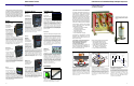
VacClad-W, the Cutler-Hammer vacuum switchgear family, has been engineered to feature a standardized design, interchangeable parts, slot and tab construction, and industry-leading vacuum interrupter technology. This world class switchgear includes the Type VCP-W Vacuum Circuit Breaker which meets both ANSI and IEC electrical standards.
VacClad-W, the Cutler-Hammer vacuum switchgear family, has been engineered to feature a standardized design, interchangeable parts, slot and tab construction, and industry-leading vacuum interrupter technology. This world class switchgear includes the Type VCP-W Vacuum Circuit Breaker which meets both ANSI and IEC electrical standards.
Cutler-Hammer Power Management Products provide the solutions to monitor and manage all aspects of an electrical distribution system. These innovative meters, relays and communications software applications make it possible to realize greater reliability, increased productivity and significant cost savings. METERS IQ Analyzer 6400/ 6600 Series The Premier Power Quality Meter The IQ Analyzer provides comprehensive diagnostic capabilities with over 150 metered values.
Cutler-Hammer Power Management Products provide the solutions to monitor and manage all aspects of an electrical distribution system. These innovative meters, relays and communications software applications make it possible to realize greater reliability, increased productivity and significant cost savings. METERS IQ Analyzer 6400/ 6600 Series The Premier Power Quality Meter The IQ Analyzer provides comprehensive diagnostic capabilities with over 150 metered values.
Cutler-Hammer Products Cutler-Hammer 5/15 kV Medium Voltage Switchgear Components Type VCP-W Vacuum Circuit Breaker… A New Level of Standardization Tools and Accessories All Type VCP-W Vacuum Circuit Breakers, regardless of voltage or interrupting capacity, have the same time proven stored energy mechanism…and are significantly smaller than conventional medium voltage drawout breakers in both size and weight. Refer to weights table on page 11.
Cutler-Hammer Products Cutler-Hammer 5/15 kV Medium Voltage Switchgear Components Type VCP-W Vacuum Circuit Breaker… A New Level of Standardization Tools and Accessories All Type VCP-W Vacuum Circuit Breakers, regardless of voltage or interrupting capacity, have the same time proven stored energy mechanism…and are significantly smaller than conventional medium voltage drawout breakers in both size and weight. Refer to weights table on page 11.
Cutler-Hammer Products Cutler-Hammer 5/15 kV Medium Voltage Switchgear Components Auxiliary Drawer Compartment Kits for Power Modules, Mini Modules, or Breaker Compartment Kit Value Added Approaches Cutler-Hammer Vacuum Circuit Breakers Are Convenient to Operate, Simple to Inspect, and Easy to Maintain These kits include all major parts used in assembling an auxiliary compartment.
Cutler-Hammer Products Cutler-Hammer 5/15 kV Medium Voltage Switchgear Components Auxiliary Drawer Compartment Kits for Power Modules, Mini Modules, or Breaker Compartment Kit Value Added Approaches Cutler-Hammer Vacuum Circuit Breakers Are Convenient to Operate, Simple to Inspect, and Easy to Maintain These kits include all major parts used in assembling an auxiliary compartment.
Cutler-Hammer 5/15 kV Medium Voltage Switchgear Components Cutler-Hammer Products No More than You Want… No Less than You Need A Modular Value-Added Approach to Circuit Protection…Exclusively from Cutler-Hammer 26-Inch Narrow Design 36-Inch Standard Design Power modules are ideal for OEMs who supply standard through complex switchgear. The OEM provides value-added items such as doors, bus, cable area compartments, instruments, relays and associated wiring.
Cutler-Hammer 5/15 kV Medium Voltage Switchgear Components Cutler-Hammer Products No More than You Want… No Less than You Need A Modular Value-Added Approach to Circuit Protection…Exclusively from Cutler-Hammer 26-Inch Narrow Design 36-Inch Standard Design Power modules are ideal for OEMs who supply standard through complex switchgear. The OEM provides value-added items such as doors, bus, cable area compartments, instruments, relays and associated wiring.
Breaker Type VCPW-ND VCP-W VCPW-SE VCP-W VCP-W Voltage Class Insulation BIL ANSI 5 kV 60 kV Interrupting Ratings 250 MVA Continuous Current 1200A IEC 3.6-7.2 kV 40-60 kV 25-31.5 kA 630-1250A ANSI 5-15 kV 60-95 kV 250-1500 MVA 1200-3000A IEC 3.6-17.5 kV 40-95 kV 25-40 kA 630-2000A ANSI 5-15 kV 60-95 kV 250-1500 MVA 1200-3000A IEC 3.6-17.
K Switch bo ards Switchboards 60-800 Single Section, 600V, 1200A max. (MCCB) 800A max. (QMQB) 60-100 Multisection, 600V, 1200A max. Service Entrance Switchboard 60-800 60-100 60-400 Main Device MCCB QMQB MCCB QMQB MCCB Masterpact Bolt-Loc Power-Lok Distribution Device Max. Voltage Max. Amperage Page No. MCCB QMQB 600V 1200A K-3 MCCB QMQB Sub-Metering 600V 1200A K-4 MCCB QMQB Sub-Metering 600V 6000A K-6 Ordering Information 1. Order main and distribution sections from pages 3-7.
Switchboards Service Entrance Switchboards Symbols Service Entrance Switchboards typically comprise three basic units: the Main device unit or cell, the utility compartment and the distribution section(s). Federal Pioneer offers a line of pre-engineered switchboards with main device ratings up to 6000A manufactured in accordance with CSA spec. C22.2 No. 31. • Listed below are the symbols used in the module selection process.
Switchboards 60-800 Series (Maximum 600 Volts, 1200 Amps) Features 1200A maximum bus design • Aluminum bus with tin plating standard; copper bus optional • Main devices are MCCB (400-1200A) and QMQB (400-800A) • 42 "X" feeder device space available (28 7/8"). • NB type branch breakers available • Split neutral design makes distribution wiring easier • Continuous ground bus • Galvanized steel construction.
Switchboards 60-100 Series (Maximum 600 Volts, 1200 Amps) Features 1200A maximum bus design • Aluminum bus with tin plating standard; copper bus optional • Main devices are MCCB circuit breakers or QMQB fusible load break switches • NB type branch breakers available • Sub-metering branch devices available up to 200A • Free standing, cable fed distribution section available • Capable of bus duct entry or exit • Galvanized steel construction with ASA 61 grey steel front covers • CSA Type 1 E
Switchboards 60-100 Main Cell Dimensional Information Switch bo ards Bus Stub (Back View) Notes: Busless wireway width (ww) is 16”, bussed wireway width (ww)is 24”. 1. For 6” wall, X = 5”; 8” wall, X = 9.5”; 12” wall, X = 13.5”. If other than standard is required, please consult factory. K 2. Y dimension and hole patterns as per local hydro requirements.
Switchboards 60-400 Series (Maximum 600 volts, 6000 Amps) • 6000A maximum bus design • Aluminum bus with tin plating standard; copper bus optional • Main devices include Masterpact Circuit Breaker, MCCB’s or Power-Lok/Bolt-Lok switches • NB type branch breakers available • Sub-metering distribution available to 200A • Free standing, cable fed distribution section available • Bottom Entry Mains available w/o wireway (except w/Power-Lok Main) • Capable of bus duct entry • Exterior finish pa
Switchboards 60-400 Main Cell Main Cell Dimensions (in) Amps Main Device CPH, PE, PX 1600 Bolt Loc CPH, PE, PX Bolt Loc 2000 PE, PX Bolt Loc Masterpact 2500 3000 Height includes channel base 5000 Bolt Loc Masterpact Power Lok Masterpact 6000 Masterpact 4000 W D ww 36 24 24 36 42 24 36 42 36 36 48 48 36 48 54/60 42 54 60 42 Bus Stub (Back View) Notes: 1. For 6”, X = 7.25; 8” wall, X = 9.25”; 12” wall, X = 13.25”. If other than standard is required, please consult factory. 2.
Switchboards 1 60-800 Main Devices Moulded Case Circuit Breakers Amps K Switch boar ds 400 600 800 1000 K-8 Trip Unit Thermal-Magnetic Thermal-Magnetic Catalogue Number CJL3400E CJL3400N Thermal-Magnetic Thermal-Magnetic Electronic Elec. w/ Gr. Flt. CJL3400H CMH36400 CK3400E-4S CK3400E-4UT 100% Electronic 100% Elec. w/ Gr. Flt. Electronic CK3400EE-4S CK3400EE-4UT CK3400N-4S Elec. w/ Gr. Flt. 100% Electronic 100% Elec. w/ Gr. Flt. CK3400N-4UT CK3400NN-4S CK3400NN-4UT Electronic Elec. w/ Gr.
Switchboards 60-100 Main Devices Moulded Case Circuit Breakers 600 800 1000 1199 Catalogue Number CMH36400 CJM3400E Thermal-Magnetic Thermal-Magnetic Electronic Elec. w/ Gr. Flt. List Price ‡ Amps Type Thermal-Magnetic Electronic Catalogue Number CPH2036 PXF361200 CJM3400N CJM3400H CK3400E-4S CK3400E-4UT Elec. w/ Gr. Flt. 100% Electronic 100 % Elec. w/ Gr. Flt. 100% Electronic PXF361200G PEF361200LI PEF361200LIG PEF361200LS 100% Electronic 100% Elec. w/ Gr. Flt.
Switchboards 60-400 Main Devices Moulded Case Circuit Breakers Amps 1600 K Switch boar ds 2000 2500 Insulated Case Circuit Breakers Trip Unit Thermal-Magnetic Electronic Catalogue Number CPH2036 PXF361600 Elec. w/ Gr. Flt. 100% Electronic 100 % Elec. w/ Gr. Flt. 100% Electronic PXF361600G PEF361600LI PEF361600LIG PEF361600LS 100 % Elec. w/ Gr. Flt. Thermal-Magnetic Electronic PEF361600LSG CPH2036 PXF362000 Elec. w/ Gr. Flt. 100% Electronic 100 % Elec. w/ Gr. Flt.
Switchboards Main Device Accessories For CJL, CJM, CMH and CK accessories, see section I.
Switchboards N Switchboard Branch Devices, Multi-pole MCCB's Type FKD 100-250A FKG 100-250A CE..E4 CE..B Switch boar ds Amps K CE..E CE..N CE..
Switchboards N Switchboard Branch Devices, Multi-pole MCCB's (continued) Type Amps Poles CJL400E CJL400E-T CJL400E-TA 300-400A Interrupting Capacity Mounting Branch Height 10 kA DOUBLE 4X 35 kA 22 kA DOUBLE 4X 100 kA 50 kA 22 kA DOUBLE 4X 65 kA 35 kA 25 kA 10 kA SINGLE 12X 3 100 kA 65 kA 35 kA 22 kA SINGLE 12X 300-600A 3 200kA 100kA 50kA 22 kA SINGLE 12X CMH 300-600A 700-800A 900-1000A 3 65 kA 65 kA 25 kA 14 kA SINGLE 16X CK400E CK400N CK400H 200-400A 3
Switchboards Switchboard Branch Devices, Single Pole MCCBs Poles Interrupting Capacity Lug Size (1) #14 - #6 Cu/Al 1 (1) #14 - 1/0 Cu/Al Catalogue No. Type HEW0015 HEW0020 Std. Single Std. Single 42 kA 42 kA 100 kA HEW1515 HEW2020 HEZ0015 Twin2 Twin2 Std. Single 65 kA 65 kA 100 kA 100 kA HEZ0020 HEZ1515 Std. Single Twin2 kA kA kA kA 65 kA 25 kA 25 kA 25 kA 100 kA 25 kA 25 kA 25 kA HEZ2020 CE1015E CE1020E CE1030E Twin2 Std. Single Std. Single Std.
Switchboards Switchboard Branch Devices, NB Breakers Federal Pioneer Switchboards accept NB type branch circuit breakers. Two methods are available for mounting these breakers into a switchboard distribution section. The first method (interior method) utilizes the same interior as the NBLP or NBDP panelboard. The interior is mounted directly on the switchboard bus. This method restricts the sum of the amperage rating on each phase to 225A (for NBLP) and 400 or 600A (for NBDP).
Switchboards Interior Method - 240 Vac, 600A Max. • Available in 60-100 and 60-400 only. • NBDP interior is mounted directly on switchboard bus. • These interiors may be fed either from main breaker(s) or directly from switchboard bus. • Choose main and branch breakers based on the maximum short circuit capacity of the system (22 kA Max, NBH). • The sum of the rating of the NB/NBH breakers connected per phase in the NBDP interior must not exceed 400 / 600A.
Switchboards Switchboard Branch Devices, NB Breakers (cont'd) NB Breakers 2 3 15-201 25-50 15-20 NB15-20 NB25-50 NB215-20 30-60 70 90-100 NB230-60 NB270 NB2P90-100 125-150 15-20 30-60 70 NB2P125-150 NB3P15-20 NB3P30-60 NB3P70 90-100 NB3P90-100 List Price ‡ (1) #14-#2 Cu-Al NBH Poles 1 (1) #14-#2 Cu-Al 2 (1) #4-2/0 Cu/Al (1) #14-1/0 Cu/Al 3 Amps 22 kA @ 120 / 240V Cat. No.
Switchboards Non-Automatic NB Switches Poles 2 3 Amps Cat. No. 60 70 100 60 NB260NA NB270NA NB2P100NA NB3P60NA 70 100 NB3P70NA NB3P100NA List Price ‡ NB Breaker Accessories Description Plastic Filler Qty. 25 BFAB HTNA 1LOB Aluminum Filler Handle Tie 1P Lockoff-Padlocking 1 1 10 2LOK 3-100LOK 1LOK 2P Lockoff-Padlocking 3P Lockoff-Padlocking 1P Lockoff-Non-Padlocking 10 10 10 List Price K Switch boar ds Cat. No.
Switchboards Metering Devices Meter Power Meter 1 PM 600 PM 620 PM650 CM-2150 CM-2250 CM-2350 CM-2450 Switchboard List Price ‡ 60-800/60100/60-400 60-100/60-400 Note: 1.
Switchboards K Switch boar ds Metering Locations K-20 ‡For prices refer to List Price Book 1199
Switchboards Switchboard Options Description Switchboard 60-800 60-100 60-400 60-800 60-100 60-400 Driphood (per cell) Door Over Distribution (per cell) Channel Base 60-800 60-100 60-400 Copper Bus (per cell) 60-800 60-100 60-4001 Single Phase Protection 60-100 60-400 Special Paint (per cell) 60-800 60-100 60-400 Description Switchoard Fibre Entry/Exit Plate 60-800 60-100 60-400 List Price ‡ 60-800 60-100 60-400 60-800 60-100 60-400 60-800 60-100 60-400 60-800 60-100 60-400 60-100 60-400 Alu
Power-Zone® 4 Low Voltage, Metal-Enclosed, Drawout Switchgear with Masterpact® NW and NT Low Voltage Power Circuit Breakers Class 6037 Catalog 05 CONTENTS Description . . . . . . . . . . . . . . . . . . . . . . . . . . . . . . . . . . . . . . . . . . . . . .Page “Product Description” . . . . . . . . . . . . . . . . . . . . . . . . . . . . . . . . . . . . . . . . . 5 “General and Application Information” . . . . . . . . . . . . . . . . . . . . . . . . . . . 11 “Technical Overview” . . . . . . . . . . . . .
Power-Zone® 4 Table of Contents TABLE OF CONTENTS TABLE OF CONTENTS......................................................................................................................... 3 PRODUCT DESCRIPTION.................................................................................................................... 5 Section Contents ............................................................................................................................. 5 Introduction ........................
Power-Zone® 4 Table of Contents Top and Bottom Conduit Entrance Layouts ................................................................................... 76 System Design .............................................................................................................................. 88 Weights .......................................................................................................................................... 90 SUGGESTED SPECIFICATIONS...................................
Power-Zone® 4 Product Description SECTION 1 : PRODUCT DESCRIPTION SECTION CONTENTS “Introduction” . . . . . . . . . . . . . . . . . . . . . . . . . . . . . . . . . . . . . . . . . . . . . . . 6 “Features and Benefits” . . . . . . . . . . . . . . . . . . . . . . . . . . . . . . . . . . . . . 6 “Compartmentalization” . . . . . . . . . . . . . . . . . . . . . . . . . . . . . . . . . . . . . 7 “UL Listing” . . . . . . . . . . . . . . . . . . . . . . . . . . . . . . . . . . . . . . . . . . . . . . .
Power-Zone® 4 Product Description INTRODUCTION Power-Zone® 4 low voltage, metal-enclosed, drawout switchgear is designed to provide superior electrical distribution, protection, and power quality management for the entire facility. The prime components of the switchgear are the Masterpact® NW and Masterpact NT ANSI-rated circuit breakers.
Power-Zone® 4 Product Description Compartmentalization Structures are compartmentalized and are built with barriers as required by ANSI C37.20.1. The structure has large conduit space within the main and feeder sections. UL Listing Power-Zone 4 switchgear is designed and engineered to comply with UL1558 requirements. Masterpact NW and NT circuit breakers are UL1066 listed. A UL label can be affixed where UL coverage exists for all component material, parts, and devices in a switchgear section.
Power-Zone® 4 Product Description Disconnecting Contacts The main disconnecting contacts (power plug-on fingers) on the rear of the circuit breaker are spring loaded and self-aligning to ensure positive electrical contact when the circuit breaker is in the connected position. The secondary disconnecting contacts are located on the top front of the circuit breaker element and are used for connecting the accessories to the control power source, other control circuits, or communication circuits.
Power-Zone® 4 Product Description Equipment Ratings Application Voltage Systems Ampacities 600 Vac Maximum 1600 A–5000 A (main circuit breaker or main lugs only) 1Ø3W, 3Ø3W, 3Ø4W 50/60 Hz Short-Circuit Current Ratings Short-Time Withstand Ratings 240 V 480 V 600 V 42 kA 42 kA 42 kA 42 kA 65 kA 65 kA 65 kA 65 kA 85 kA 85 kA 85 kA 85 kA 200 kA 200 kA 130 kA 100 kA (maximum) 9 11/2005 © 2005 Schneider Electric All Rights Reserved
Power-Zone® 4 Product Description 10 © 2005 Schneider Electric All Rights Reserved 11/2005
Power-Zone® 4 General and Application Information SECTION 2 : GENERAL AND APPLICATION INFORMATION SECTION CONTENTS “Introduction” . . . . . . . . . . . . . . . . . . . . . . . . . . . . . . . . . . . . . . . . . . . . . . 12 “Structure” . . . . . . . . . . . . . . . . . . . . . . . . . . . . . . . . . . . . . . . . . . . . . . . . 13 “Enclosures” . . . . . . . . . . . . . . . . . . . . . . . . . . . . . . . . . . . . . . . . . . . . . . . 15 “Control and Communications Wiring” . . . . . . . . . . . . . . .
Power-Zone® 4 General and Application Information INTRODUCTION Power-Zone® 4 switchgear with Masterpact® NW and NT circuit breakers provides the optimal switchgear solution in an industrial environment. The switchgear is designed for ease of use, system selectivity, system uptime, and low maintenance. The switchgear is easy to operate and maintain because of the technological advances in communications, power quality monitoring, and measuring capabilities.
Power-Zone® 4 General and Application Information STRUCTURE The switchgear assembly is composed of vertical sections arranged according to customer requirements. Each section is divided into a maximum of four compartments when using Masterpact NW circuit breakers, or a maximum of eight compartments when using Masterpact NT circuit breakers. One or more of these compartments can be used as an auxiliary instrument compartment containing potential transformers, meters, relays, and control devices.
Power-Zone® 4 General and Application Information The examples below depict a typical Power-Zone 4 switchgear assembly.
Power-Zone® 4 General and Application Information ENCLOSURES NEMA Type 1 Indoor Enclosures The standard Power-Zone 4 switchgear enclosure is NEMA Type 1, general purpose. NEMA Type 1 enclosures are dead front, metal-enclosed structures. All sheet steel parts of the enclosure, inside and out, are painted using an electro-deposition process.
Power-Zone® 4 General and Application Information NEMA Type 3R Walk-In Enclosures Power-Zone 4 switchgear is also available in a NEMA Type 3R walk-in enclosure for outdoor installation.
Power-Zone® 4 General and Application Information Control and Communications Wiring Figure 6: Conduit Entrances Control and communication wiring is installed and connected from the front of the switchgear. The secondary wiring design allows for circuit breaker compartment wiring without removing the circuit breaker from its compartment. Control Conduit Entrances The control wiring conduit entrance is in both the top and bottom of each section for maximum flexibility.
Power-Zone® 4 General and Application Information Figure 7: Secondary Wiring System Vertical wireway Secondary horizontal wireway Control wiring Secondary disconnecting contacts Shutters (optional) Secondary terminal block Secondary disconnecting terminals Standard Features: • Control wires in wiring trough above the circuit breaker compartment • Secondary terminal block originates directly from the circuit breaker without the use of an intermediate terminal block for factory and customer wirin
Power-Zone® 4 General and Application Information Rear Cable Compartment The rear cable compartment is located behind the bus compartment. It provides room for rear access cable installation. Silver plated copper load bars extend from the load side of the circuit breaker’s stationary connecting contacts into the cable compartment. Cable terminations on the load bars permit cables to exit through either the top or bottom of the vertical sections.
Power-Zone® 4 General and Application Information Bus Compartment The bus compartment contains the horizontal and vertical bus, and is located between the circuit breaker compartment and the cable compartment. The bus compartment is separated from the circuit breaker compartment with grounded steel barriers. The optional side and rear barriers isolate the bus compartment from the rear cable compartment.
Power-Zone® 4 General and Application Information Auxiliary Instrument Compartments Auxiliary instrument compartments are the same size as circuit breaker compartments. Typical auxiliary instrument compartments contain control power transformers, control components, meters, relays, and other optional devices. Circuit monitor displays and other metering devices can be mounted on the door.
Power-Zone® 4 General and Application Information Figure 12: Circuit Breaker Lifter Bar The circuit breaker lifter bar is used with both 3-pole and 6-pole Masterpact NW circuit breakers. The size of the circuit breaker determines whether the inside or outside notches on the lifter bar will be used. Traveling Lifter Assembly A rail-mounted, traveling type, circuit breaker lifting device is optionally available with indoor type switchgear.
Power-Zone® 4 General and Application Information Figure 14: Through-the-Door Construction Through-the-Door Construction Powerlogic circuit monitor display (optional) The closing and opening push buttons, the racking handle, and racking mechanism are accessible through the front door cutout, allowing circuit breaker operation and disconnection without opening the door. Optional shutters (see "Secondary Wiring System" on page 18) can be provided, covering live parts when the circuit breaker is removed.
Power-Zone® 4 General and Application Information Interrupting and Short-Time (Withstand) Capability Power-Zone 4 switchgear with Masterpact NW circuit breakers have the highest interrupting (200,000 A at 480 V without using fuses) and short-time (withstand) ratings for low voltage switchgear in the smallest physical size. The small switchgear footprint and the elimination of limiters reduces cost.
Power-Zone® 4 General and Application Information Circuit Breaker Parts The Masterpact® NW circuit breaker has fewer parts than conventional circuit beakers while performing the same functions.
Power-Zone® 4 General and Application Information Circuit Breaker Operation Power-Zone 4 switchgear with Masterpact NW and NT circuit breakers has through-the-door circuit breaker racking. The connect, test, and disconnect positions can be made with the circuit breaker compartment door closed.
Power-Zone® 4 General and Application Information Two-Step Stored Energy Mechanism Figure 18: Charging the Closing Springs Masterpact NW and NT circuit breakers are stored energy devices with a two-step operating mechanism.
Power-Zone® 4 General and Application Information Circuit Breaker and Equipment Accessories A number of Masterpact NW and NT circuit breaker accessories are available with Power-Zone 4 switchgear. A few of the most common accessories are listed below. Shutters: Optional shutters in the cradle automatically block access to the main disconnects when the circuit breaker is in the disconnect, test, or remove position. An optional padlock attachment to lock shutters closed is also available.
Power-Zone® 4 General and Application Information Micrologic® Trip Units A new family of field-installable trip units is available with Masterpact® NW and NT circuit breakers. The circuit breaker overcurrent protection consists of a solid-state, microprocessor-based tripping device that requires no external power source. The complete tripping system has three main components: the molded sensors, the trip device (with rating plug), and the trip actuator.
Power-Zone® 4 General and Application Information Type P (Power Metering) Trip Unit Standard Trip Features: Available Options: • All standard features of Micrologic Type A trip unit • • • LSI trip configuration LSIG (ground fault trip with programmable ground fault alarm) • Test kits Incremental “fine tuning” of L, S, I, and, when selected, G pickup and delay settings • LCD dot matrix display and LED trip indication • • Advanced user interface Advanced user protection (includes, but not limite
Power-Zone® 4 General and Application Information Powerlogic System Power-Zone 4 switchgear is available with Powerlogic® metering, data acquisition, and control system features. The Powerlogic system is used in conjunction with Micrologic® Type A, Type P, and Type H trip units for the Masterpact NW and NT circuit breakers.
Power-Zone® 4 General and Application Information System Communications The Powerlogic®, monitoring system, as well as Transparent Ready® Web Enabled (TRE) equipment, is available, as an option, with Power-Zone 4 switchgear. The Powerlogic power monitoring and control systems, and (TRE) systems use a high-performance ethernet backbone with Modbus® communications.
Power-Zone® 4 General and Application Information System Components Powerlogic® system components and additional features are listed below.
Power-Zone® 4 General and Application Information ARC FLASH PROTECTION WITH MASTERPACT NW CIRCUIT BREAKERS What is an Arc Flash? An arc flash occurs when insulation or isolation between electrified conductors is breached or can no longer withstand the applied voltage. As employees work on or near energized conductors or circuits, movement near or contact with the equipment (or a failure of the equipment) may cause a phase-toground and/or a phase-to-phase fault.
Power-Zone® 4 General and Application Information Calculating Arc Flash Incident energy using Masterpact NW L1F circuit breakers Example 1: Bolted fault currents at MCC is Ib = 17kA, bolted fault current at PDP is Ib = 40kA. Using the following Masterpact NW-LF equations from actual testing, we calculate the incident energy to be 1.15 cal/cm2 at the MCC and 3.31 cal/cm2 at the PDP. This allows workers to wear Class 0 and 1 PPE per NFPA 70E when working on or around energized parts.
Power-Zone® 4 General and Application Information 36 © 2005 Schneider Electric All Rights Reserved 11/2005
Power-Zone® 4 Technical Overview SECTION 3 : TECHNICAL OVERVIEW SECTION CONTENTS “Introduction” n . . . . . . . . . . . . . . . . . . . . . . . . . . . . . . . . . . . . . . . . . . . . . 38 “Power-Zone 4 Switchgear Ratings” . . . . . . . . . . . . . . . . . . . . . . . . . . . 38 “Masterpact NW and NT Circuit Breakers” . . . . . . . . . . . . . . . . . . . . . . 38 “Micrologic Trip Units” . . . . . . . . . . . . . . . . . . . . . . . . . . . . . . . . . . . . . . 41 “Trip Curves” . . . . . . . . . . . . .
Power-Zone® 4 Technical Overview INTRODUCTION This section contains basic technical information pertaining to the Power-Zone 4 switchgear, Masterpact® NW and NT circuit breakers, and Micrologic® trip units. Power-Zone 4 Switchgear Ratings Power-Zone 4 switchgear is industrial-duty equipment built to ANSI standards and uses 100% rated Masterpact NW and NT circuit breakers. Switchgear ratings are listed below.
Power-Zone® 4 Technical Overview Table 1: Masterpact NW and NT Circuit Breaker Interrupting Rating Trip Current Range Circuit Breaker Model # 40–800 40–800 Instantaneous Trip Rating (A) Short-time Trip Rating (A) 208 V–240 V (254 V Max.) 480 V (508 V Max.) 600 V (635 V Max.) 208 V–240 V (254 V Max.) 480 V (508 V Max.) 600 V (635 V Max.
Power-Zone® 4 Technical Overview Table 2: Various Sensor Capacities of Masterpact NW and NT Circuit Breakers.
Power-Zone® 4 Technical Overview Key Interlock Operation As shown in the example below, a main-tie-main manual key interlock scheme is designed to keep all three circuit breakers from being closed simultaneously. Only two of the three circuit breakers can be closed simultaneously. NOTE: Spare keys should be removed and kept safely stored and under the control of responsible supervision.
Power-Zone® 4 Technical Overview Functionality The table below lists the standard and optional trip unit features for Micrologic Type A (Ammeter), Type P (Power Metering), and Type H (Harmonics) trip units for use in Power-Zone 4 switchgear.
Power-Zone® 4 Technical Overview Trip Curves This section contains typical characteristic trip curves for Micrologic trip units in Power-Zone 4 switchgear. Detailed information about Micrologic trip units can be found in the Masterpact NW circuit breaker catalog. • “Typical Micrologic 6.0 A/P/H Trip Units with Adjustable Ground-fault Pickup and Delay (Ground Fault I2t OFF and ON / In < 400 A)” on page 44 • “Typical Micrologic 6.
Power-Zone® 4 Technical Overview Figure 23: Typical Micrologic 6.0 A/P/H Trip Units with Adjustable Ground-fault Pickup and Delay (Ground Fault I2t OFF and ON / In < 400 A) 8 9 10 7 6 5 4 3 2 1.5 .8 .9 1 .7 .6 .5 .4 .3 .2 .15 .07 .08 .09 .1 .06 .05 B48095-613-01.
Power-Zone® 4 Technical Overview Figure 24: Typical Micrologic 6.0 A/P/H Trip Units with Adjustable Ground-fault Pickup and Delay (Ground Fault I2t OFF and ON / 400 A < In < 1200 A) Micrologic 6.
Power-Zone® 4 Technical Overview Figure 25: Typical Micrologic 6.0 A/P/H Trip Units with Adjustable Ground-fault Pickup and Delay (Ground fault I2t OFF and ON / In > 1200A) B48095-613-03.eps Micrologic 6.
Power-Zone® 4 Technical Overview Figure 26: Typical Micrologic 5.0/6.0 A/P/H Trip Units (Long-time Pickup and Delay / Shorttime Pickup and I2t OFF Delay) B48095-613-04.eps Micrologic 5.0/6.0 A/P/H Trip Units Characteristic Trip Curve No. 613-4 80 90 100 70 60 50 40 30 20 15 8 9 10 7 6 5 4 3 2 1.5 .7 .8 .9 1 .6 .
Power-Zone® 4 Technical Overview Figure 27: Typical Micrologic 5.0/6.0 A/P/H Trip Units (Short-time Pickup and I2t ON Delay) Micrologic 5.0/6.0 A/P/H Trip Units 80 90 100 70 60 50 40 30 20 15 8 9 10 7 6 5 4 3 2 1.5 .8 .9 1 .7 .6 .
Power-Zone® 4 Technical Overview g Figure p28: g Typical g Micrologic p 3.0 A Trip y Unit (Long-time Pickup and Delay) Micrologic 3.0A Trip Unit 80 90 100 70 60 50 40 30 20 15 8 9 10 7 6 5 4 3 2 1.5 .8 .9 1 .7 .6 .
Power-Zone® 4 Technical Overview Figure 29: Typical Micrologic 5.0/6.0 Trip Units (instantaneous Pickup, 2X to 15X and OFF) Micrologic 5.0/6.0 Trip Units 80 90 100 70 60 50 40 30 20 15 8 9 10 7 6 5 4 3 2 1.5 .7 .8 .9 1 .6 .
Power-Zone® 4 Technical Overview Figure 30: Typical Micrologic 3.0 A Trip Unit (Instantaneous Pickup, 1.5X to 12X) Micrologic 3.0A Trip Unit Characteristic Trip Curve No. 613-8 80 90 100 70 60 50 40 30 20 15 8 9 10 7 6 5 4 3 2 1.5 .8 .9 1 .7 .6 .
Power-Zone® 4 Technical Overview Figure 31: Typical Micrologic 2.0 A Trip Unit (Long-time Pickup and Delay / Short-time Pickup and Delay) Micrologic 2.0A Trip Unit Characteristic Trip Curve No. 613-9 80 90 100 70 60 50 40 30 20 15 8 9 10 7 6 5 4 3 2 1.5 .8 .9 1 .7 .6 .5 B48095-613-09.
Power-Zone® 4 Technical Overview Figure 32: Micrologic 2.0/3.0/5.0/6.0 A/P/H Trip Unit Instantaneous Override Values Instantaneous Override Values MASTERPACT NW/NT NW08N1 a NW08N1 NW16N1 NW08H1 a NW08H1 NW16H1 NW20H1 NW32H1 NW08H2 a NW08H2 NW16H2 NW20H2 NW32H2 NW40H2 NW50H2 NW08H3 a NW08H3 NW16H3 NW20H3 NW32H3 NW40H3 NW50H3 NW08L1 a NW08L1 NW08L1F NW16L1 NW16L1F NW20L1 NW20L1F NW32L1 NW40L1 NW50L1 Inst.
Power-Zone® 4 Technical Overview Selection Tables with Transformer Ratings Transformer ratings for Masterpact NW circuit breakers in Power-Zone 4 switchgear are listed below. Table 6: Application of Masterpact NW Circuit Breakers (with Standard Three-Phase Transformers: Liquid Filled and Ventilated Dry Types) Transformer Base (100%) Rating kVA and Percent Impedance Amperes a Max.
Power-Zone® 4 Technical Overview Table 6: Application of Masterpact NW Circuit Breakers (with Standard Three-Phase Transformers: Liquid Filled and Ventilated Dry Types) Transformer Base (100%) Rating kVA and Percent Impedance Amperes a Max.
Power-Zone® 4 Technical Overview Table 6: Application of Masterpact NW Circuit Breakers (with Standard Three-Phase Transformers: Liquid Filled and Ventilated Dry Types) Transformer Base (100%) Rating kVA and Percent Impedance Amperes a Max.
Power-Zone® 4 Technical Overview Table 6: Application of Masterpact NW Circuit Breakers (with Standard Three-Phase Transformers: Liquid Filled and Ventilated Dry Types) Transformer Base (100%) Rating kVA and Percent Impedance 3000 5.75% 3750 5.75% 3750 5.75% Amperes a 3609 4511 4511 Secondary Short-Circuit Currents RMS Symmetrical Amperes Minimum Size Circuit Breakers for Selective Trip Systems Max.
Power-Zone® 4 Technical Overview Table 6: Application of Masterpact NW Circuit Breakers (with Standard Three-Phase Transformers: Liquid Filled and Ventilated Dry Types) Transformer Base (100%) Rating kVA and Percent Impedance Amperes a Max.
Power-Zone® 4 Technical Overview Table 6: Application of Masterpact NW Circuit Breakers (with Standard Three-Phase Transformers: Liquid Filled and Ventilated Dry Types) Transformer Base (100%) Rating kVA and Percent Impedance 3750 5.75% Amperes a 3608 Secondary Short-Circuit Currents RMS Symmetrical Amperes Minimum Size Circuit Breakers for Selective Trip Systems Max.
Power-Zone® 4 Technical Overview Distribution Systems This section contains a brief overview of Wye and Delta distribution systems. Wye Solidly Grounded Systems A Wye system is the most common type of three-phase distribution system for low voltage switchgear.
Power-Zone® 4 Technical Overview Delta Grounded and Ungrounded Systems Formerly common, Delta three-wire systems are rarely used in low voltage distribution systems. Delta three-wire distribution systems can be grounded or ungrounded services. Generally, Delta systems are ungrounded. In some cases, they are grounded on the “corner” of the delta or some other point. Ungrounded Delta systems do not have a reference point or ground.
Power-Zone® 4 Technical Overview Ground faults are an inadvertent flow of current between the normal current-carrying conductors and ground. These ground faults usually start at a low level and, if left undetected, escalate causing significant heat and mechanical damage to the electrical system. Ground faults can escalate to a phase-to-phase fault causing major system damage.
Power-Zone® 4 Technical Overview Residual Ground Fault Sensing Residual ground fault sensing systems use one current sensor for each current-carrying conductor. The trip unit vectorially sums the secondary outputs from each sensor to determine if there is a ground fault and the magnitude of the ground fault. The following diagram shows the current sensors for a three-phase, four-wire system. There is a current sensor on each phase and the neutral.
Power-Zone® 4 Technical Overview The current sensor and ground fault interface module must be wired per the installation and wiring instructions included with the ground fault interface module. Modified Differential Ground Fault System A modified differential ground fault system (MDGF) is used for multiple sourced systems. Normal residual and ground-source return systems will not correctly sum all of the circulating currents caused by the multiple neutral paths and multiple grounds.
Power-Zone® 4 Technical Overview High Resistance Grounded Systems When continuance of service for a distribution system is a high priority, high-resistance grounding adds the features of a grounded system on an ungrounded system, while minimizing the risk of service interruptions resulting from ground faults.
Power-Zone® 4 Technical Overview Delta Systems Configured A neutral point must be established in an ungrounded Delta-connected system using three singlephase transformers. Typically, grounding resistors and transformers are chosen to limit the ground current to a maximum value of five amperes. This technique can be applied on Wye-connected sources when the neutral point is not accessible from the service entrance conduit. The neutral point cannot be used to service phase-to-neutral loads.
Power-Zone® 4 Technical Overview Automatic Transfer Systems Automatic transfer systems minimize power interruption by transferring the load from the normal source to an alternate source when the normal source is temporarily unavailable. The system uses multiple connections to power sources, usually utility sources, and a programmable logic controller (PLC) to achieve this transfer. These systems also feature redundant supplies of control power.
Power-Zone® 4 Technical Overview Main-Tie-Main Circuit Breakers Both main circuit breakers, connected to a utility source, are connected together by means of a normally open tie circuit breaker. Each main circuit breaker feeds independent load buses. Various settings of the preferred source selector switch and the retransfer on/off options determine which circuit breakers are closed during various operating conditions.
Power-Zone® 4 Wiring Diagrams SECTION 4 : WIRING DIAGRAMS SECTION CONTENTS “Basic Electrically Operated Circuit Breaker Diagrams” . . . . . . . . . . . . . . 70 “Masterpact NW/NT Alarm and Cradle Contacts” . . . . . . . . . . . . . . . . 70 “Masterpact NW/NT Power, Trip Unit, and Remote Operation” . . . . . .
Power-Zone® 4 Wiring Diagrams BASIC ELECTRICALLY OPERATED CIRCUIT BREAKER DIAGRAMS This section contains Masterpact® NW and NT circuit breaker diagrams. Refer to the Masterpact NT/NW Universal Power Circuit Breakers catalog for additional information. Masterpact NW/NT Alarm and Cradle Contacts Masterpact NW Alarm and Cradle Contacts 914 912 934 CE1 932 924 922 CE2 314 324 312 332 832 Test position EF OF . . OF . . OF1 ..8 ..6 ..2 ..
Power-Zone® 4 Wiring Diagrams Masterpact NT Alarm and Cradle Contacts 914 912 324 312 CE1 314 334 322 911 331 Alarm contacts CT1 311 CE3 321 CD1 821 11 21 31 CE2 Test position OF1 CD2 41 824 812 814 822 12 14 22 OF2 Connected Disconnected 811 OF3 24 32 Closed 34 42 OF4 44 Open 332 Figure 45: Cradle contacts OF4 OF3 OF2 OF1 CD2 CD1 CE3 CE2 CE1 CT1 44 34 24 14 824 814 334 324 314 914 42 32 22 12 822 812 332 322 312 912 41 31 21 11 811
Power-Zone® 4 Wiring Diagrams Masterpact NW/NT Power, Trip Unit, and Remote Operation B3 B2 252 254 A3 A2 C3 C2 C13 C12 D2 84 K2 82 182 184 Q3 Q2 484 Q1 474 Z5 Z4 Z1 Z2 Z3 V2 V3 BPF BPO AT M6C VN V1 Charged Fault Downstream Upstream C Fault B Z1 N A Masterpact NW Power, Trip Unit, and Remote Operation Z3 Z4, Z5 Z2 Figure 46: MCH PF UC1 UC2 B1 A1 C1 C11 D1 81 181 Trip unit COM XF MX1 or or 471 F2+ T4 F1– T3 T2 T1 M3 M2 M1 Power MX2 Res M6C or
Power-Zone® 4 Wiring Diagrams Remote Operation Charged Fault Z5 Z4 Z2 Z5 Downstream Circuit Breaker Z1 Z4 Upstream Circuit Breaker L3 Z3 L2 Z2 L1 Z1 N Z3 Power Masterpact NT Power, Trip Unit, and Remote Operation Fault Figure 47: B3 B2 252 254 A3 A2 C3 C2 C12 D2 84 K2 82 182 184 Q3 Q2 Q1 484 474 Z5 Z4 Z3 Z2 Z1 V3 V2 V1 VN M6C MCH Q S2 SDE2 SDE1 V MX1 XF CH PF RES UC1 A1 24 Vdc Trip unit COM C1 D1 81 181 471 F2+ F1 T4 T4 T3 T2 T3 T1 T2
Power-Zone® 4 Wiring Diagrams NW/NT Circuit Breaker Trip Units and Remote Operation Table 9: Basic A/P/H Trip Units Basic A P H Trip Unit ■ ■ ■ ■ Com: E1–E6 communication ■ ■ ■ ■ ■ ■ ■ ■ ■ ■ ■ ■ ■ ■ ■ UC1: Z1–Z5 logical selectivity Z1 = ZSI OUT Z2 = ZSI OUT Com; Z3 = ZSI IN Com Z4 = ZSI IN short-time delay Z5 = ZSI IN ground fault ■ ■ ■ UC2: T1, T2, T3, T4 = external neutral; ■ ■ ■ ■ ■ UC3: F2+, F1– 24 Vdc external power supply External neutral VN plug ■ ■ UC4 ■ ■ ■ ■ M2C o
Power-Zone® 4 Dimensions SECTION 5 : DIMENSIONS SECTION CONTENTS “Top and Bottom Conduit Entrance Layouts” . . . . . . . . . . . . . . . . . . . . . . 76 “System Design” . . . . . . . . . . . . . . . . . . . . . . . . . . . . . . . . . . . . . . . . . . . 88 “Weights” . . . . . . . . . . . . . . . . . . . . . . . . . . . . . . . . . . . . . . . . . . . . . . . . . .
Power-Zone® 4 Dimensions TOP AND BOTTOM CONDUIT ENTRANCE LAYOUTS Figure 48: Top and Bottom Conduit Entrance Dimensions (22-inch wide)– Not for Construction (consult factory drawings) 17.00 432 2.50 64 17.00 432 2.50 17.00 64 432 2.50 64 34.00 864 23.00 584 17.00 432 72.00 1829 54.00 5.00 60.00 5.00 127 1524 127 1372 5.00 127 4.00 4.00 102 102 4.00 102 12.00 12.00 12.00 305 305 305 2.0 2.0 34 34 2.0 34 Top Conduit Entrance–Auxiliary Section (22-inch wide) 3.50 89 3.
Power-Zone® 4 Dimensions Figure 49: Top and Bottom Conduit Entrance Dimensions (30-inch wide)– Not for Construction (consult factory drawings) 2.50 64 2.50 64 2.50 64 25.00 635 25.00 635 25.00 635 34.00 864 23.00 584 17.00 432 72.00 1829 54.00 1372 60.00 1524 5.00 127 5.00 127 5.00 127 4.00 102 4.00 102 4.00 102 12.00 305 12.00 305 12.00 305 2.00 51 2.00 51 2.00 51 Top Conduit Entrance–Auxiliary Section (30-inch wide) 25.00 635 25.00 25.00 635 635 33.00 838 16.00 406 22.
Power-Zone® 4 Dimensions Figure 50: Top and Bottom Conduit Entrance Dimensions (36-inch wide)– Not for Construction (consult factory drawings) 31.00 787 2.50 64 31.00 787 2.50 31.00 64 787 2.50 64 34.00 864 23.00 584 17.00 432 72.00 1829 5.00 54.00 127 1372 60.00 5.00 5.00 1524 127 127 4.00 4.00 102 102 4.00 102 12.00 12.00 12.00 305 305 305 2.0 2.0 34 34 2.0 34 Top Conduit Entrance–Auxiliary Section (36-inch wide) 3.50 89 3.50 89 3.50 89 33.00 838 22.00 559 16.
Power-Zone® 4 Dimensions Figure 51: Top and Bottom Conduit Entrance Dimensions (22-inch wide Main, Tie, and Feeder Sections)– Not for Construction (consult factory drawings) 17.00 432 2.50 64 17.00 432 2.50 17.00 64 432 2.50 64 27.00 686 15.00 381 9.00 229 72.00 1829 5.00 54.00 127 1372 60.00 5.00 1524 127 5.00 127 4.00 4.00 102 102 4.00 102 12.00 12.00 12.00 305 305 305 2.0 2.0 34 34 2.
Power-Zone® 4 Dimensions Figure 52: Top and Bottom Conduit Entrance Dimensions (30-inch wide Main, Tie, and Feeder Sections)– Not for Construction (consult factory drawings) 2.50 64 2.50 64 2.50 64 25.00 635 25.00 635 25.00 635 27.00 686 15.00 381 9.00 229 72.00 1829 54.00 1372 60.00 1524 5.00 127 5.00 127 5.00 127 4.00 102 4.00 102 4.00 102 12.00 305 12.00 305 12.00 305 2.00 51 2.00 51 2.
Power-Zone® 4 Dimensions Figure 53: Top and Bottom Conduit Entrance Dimensions (36-inch wide Main, Tie, and Feeder Sections)– Not for Construction (consult factory drawings) 31.00 787 2.50 64 31.00 787 2.50 31.00 64 787 2.50 64 27.00 686 15.00 381 9.00 229 72.00 1829 54.00 5.00 60.00 5.00 127 1524 127 1372 5.00 127 4.00 4.00 102 102 4.00 102 12.00 12.00 12.00 305 305 305 2.0 2.0 34 34 2.
Power-Zone® 4 Dimensions Figure 54: NEMA 3R Walk-in Low Voltage Switchboard/Switchgear Top Conduit Entrance Dimensions–Not for Construction (consult factory drawings) 5.42 (138) 31.00 5.42 (138) 4.00 (102) 13.00 75.23 (1918.65) Busway 11.25 25.77 (656) 4.00 (102) 4.00 (102) 15.51 47.00(1194) 13.96 (355) Figure 55: 26.00 3.86 (102) Exhaust Fan NEMA 3R Walk-in Low Voltage Switchboard/Switchgear Bottom Conduit Entrance Dimensions–Not for Construction (consult factory drawings) 2.8 (71) 2.
Power-Zone® 4 Dimensions Figure 56: Front Elevation Dimensions–Not for Construction (consult factory drawings) Table 11: AB Typical Auxiliary–A (22-inch wide) Location Description AB Blank or instrument CD Blank or instrument AB 91.50 91.50 2,324 2324 Table 12: CD Typical Auxiliary–B (36-inch wide) Location Description AB Blank or instrument CD Blank or instrument CD 22.00 36.
Power-Zone® 4 Dimensions Figure 57: A 91.50 2324 Front Elevation Dimensions–Not for Construction (consult factory drawings) Table 13: Typical Main and Tie–C (36-inch wide) Locatio n Description Frame Size Frame SCCR A Blank or instrument – – BC Main or tie 4000 A–5000 A H2 D Feeder 800 A–2000 A A B N1–H2 91.
Power-Zone® 4 Dimensions Figure 58: Front Elevation Dimensions–Not for Construction (consult factory drawings) Table 17: Typical Feeder–D (36-inch wide) A B 91.50 Location Description Frame Size Frame SCCR A Feeder 800 A–2000 A N1–H2, L1F B Feeder 800 A–2000 A N1–H2, L1F CD Feeder 4000 A–5000 A H2 Table 18: 2324 CD Typical Feeder–E (36-inch wide) Locatio n Description Frame Size Frame SCCR AB Feeder 4000 A–5000 A H2 CD Feeder 4000 A–5000 A H2 AB 91.50 2324 CD 36.
Power-Zone® 4 Dimensions Figure 59: Front Elevation Dimensions–Not for Construction (consult factory drawings) Table 19: Typical Feeder–F (30-inch wide) A Locatio n B 91.50 2324 C 1 2 Description Frame Size Frame SCCR A Feeder 800 A–2000 A N1–H2, L1F A1/A2 Feeder 800 A NT N1 B Feeder 800 A–2000 A N1–H2, L1F B1/B2 Feeder 800 A NT N1 C Feeder 800 A–2000 A N1–H2, L1F C1/C2 Feeder 800 A NT N1 D Feeder 800 A–2000 A N1–H2, L1F D1/D2 Feeder 800 A NT N1 D 30.
Power-Zone® 4 Dimensions Figure 61: Right Side View, NEMA 3R Walk-in Low Voltage Switchboard/Switchgear 4.0 (102) 3.86 (96) 20.0 (508) 38.0 (966) 13.96 (355) 81.89 (2080) 93.8 (2383) 37.42 (951) 84.0 (2134) 118.0 88.0 (2298) (2235) 36.0 (915) 47.0 (1194) 74.
Power-Zone® 4 Dimensions SYSTEM DESIGN Figure 62: 91.50 Front Elevation Dimensions–Not for Construction (consult factory drawings) Feeder Feeder Feeder Feeder Tie Main 1 Main 2 2324 Feeder Feeder Feeder Feeder Feeder Feeder Feeder 22.00 22.00 22.00 22.00 22.00 559 559 559 559 559 66.00 44.00 1676 1118 110.
Power-Zone® 4 Dimensions Figure 63: Front Elevation Dimensions–Not for Construction (consult factory drawings) Feeder Feeder 91.50 Main 2324 Feeder Feeder Feeder 36.00 22.00 914 559 Feeder 22.00 559 36.00 44.00 914 1118 80.
Power-Zone® 4 Dimensions WEIGHTS Refer to the shipping documents for the correct weights and dimensions. The weights given here are approximate values. Consult shipping documents for actual weights. Table 20: Switchgear 4 High without Circuit Breakers 22 Wide 36 Wide Bus Rating lbs 1600 A–2000 A 1200 Kg 545 lbs 1300 Kg 591 3200 A 1400 636 1500 682 40000 A–5000 A 1700 773 1800 818 Table 21: Masterpact NW Circuit Breaker Weights Amperes Lbs. Kg.
Power-Zone® 4 Suggested Specifications SECTION 6 : SUGGESTED SPECIFICATIONS SECTION CONTENTS “General” . . . . . . . . . . . . . . . . . . . . . . . . . . . . . . . . . . . . . . . . . . . . . . . . . 92 “Standards” . . . . . . . . . . . . . . . . . . . . . . . . . . . . . . . . . . . . . . . . . . . . . . 92 “Ratings” . . . . . . . . . . . . . . . . . . . . . . . . . . . . . . . . . . . . . . . . . . . . . . . . 92 “Products” . . . . . . . . . . . . . . . . . . . . . . . . . . . . . . . . . . . . . . . .
Power-Zone® 4 Suggested Specifications GENERAL This specification and associated drawings describe Power-Zone 4 switchgear constructed to ANSI C37.20.1 industry standards. The main components of the switchgear are Masterpact® NW and NT circuit breakers. NOTE: Square D Type Masterpact circuit breakers are described in “Square D Specifications, Section 16410-5–Low Voltage Power Circuit Breakers”.
Power-Zone® 4 Suggested Specifications Available short-circuit current ratings are outlined below.
Power-Zone® 4 Suggested Specifications Masterpact NW and NT Circuit Breakers A. Each circuit breaker shall be mounted in its own barriered compartment. B. Feeder circuit breakers rated 2000 A or less shall be capable of being mounted in the uppermost compartment without de-rating. C. The front of the circuit breaker shall protrude through the door of the switchgear allowing access to circuit breaker controls, indicators, and the trip unit. D.
Power-Zone® 4 Suggested Specifications Cable Compartment A. All incoming or outgoing power conductors shall be routed through the rear cable compartment. B. Feeder circuit breakers shall have adequate wire bending space, regardless of the circuit breaker interrupting rating. The table below lists the section depth needed to meet wire bending requirements. Feeder Circuit Breaker Section Depth (inches) 800 A (max.) 54 4000 A (max.) 60 4000 A (max.) 72 (optional) 4000 A (max.) 80 (optional) C.
Power-Zone® 4 Suggested Specifications Functions Basic Type A Type P Type H LSIG/ground fault trip – O X X Ground fault alarm (no trip) – – X X Ground fault trip and programming alarm – – O O Adjustable rating plugs X X X X LED – long–time pickup X X X X LED – trip indication – X X X Digital ammeter – X X X Phase loading bar graph – X X X Zone selective interlocking – X X X Communications – O X X LCD dot matrix display – – X X Advanced user interfa
Power-Zone® 4 A accessory terminals 17 application circuit breaker 7–8 seismic 8 voltage systems 9 applications high altitude 68 seismic 68 arc chutes 27 Arc Flash 34 automatic transfer systems 67 auxiliary connection wiring 18 sections 21 switches 28 auxiliary instrument compartment circuit monitor display 21 control components 21 control power transformers 21 meters 21 potential transformers 21 relays 21 B bus compartment current transformers 20 ground bus 20 horizontal cross bus 20 main bus 20 neutral
Power-Zone® 4 through-the-door construction 23 typical assembly 13 system design 3 bay representation 89 5 bay representation 88 T terminal connections 19 through-the-door construction 23 transformer ratings 54 traveling lifter assembly 22 trip units basic 29 curves 43–51 features and benefits 6, 29 functionality matrix 42 Powerlogic® data communication s 6, 28 ratings 41 type A (ammeter) 29 type H (harmonics) 30 type P (power metering) 30 U UL 1008 67 V vertical bus risers wireway 20 17 W wiring hori
Power-Zone® 4 99 11/2005 © 2005 Schneider Electric All Rights Reserved
Schneider Electric USA Schneider Electric Canada 8821 Garners Ferry Road Columbia, SC 29209 USA 1-888-SquareD (1-888-778-2733) www.us.SquareD.com 19 Waterman Avenue, M4B 1 Y2 Toronto, Ontario 1-800-565-6699 www.schneider-electric.
Gain energy insight and control with PowerLogic™ PowerLogic ION7300 series power and energy meter
Features Measurements Financial management including accounting and billing Bidirectional, absolute, and net energy measurements. Rolling block, predicted, and thermal demand. Individual and total harmonic distortion up to the 31st. Advanced logic and mathematical functions. Internet-enabled communications Facility and energy management Operations management including engineering, planning and maintenance Two RS-485 ports, infrared data port standard.
PowerLogic ION7300 series Schneider Electric PowerLogic ION7300 series meters offer unmatched value, functionality, and ease of use. Used in enterprise energy management applications such as feeder monitoring and sub-metering, PowerLogic ION7300 series meters interface with ION Enterprise software or other power management or automation systems to provide users with real-time information for monitoring and analysis.
Installation 92 m 3.6 m “ 96 m 3.7 m 8“ 96 m 3.7 m 8“ Standard PowerLogic ION7300 series meters with integrated display are designed to fit into DIN standard 92 X 92 mm (3.62 x 3.62 in.) cutout. Simply slide the mounting bars into the grooves on either side of the unit.
Power and energy measurements Fully bi-directional, 4-quadrant, revenue-accurate or revenue-certified energy metering. They can replace discrete energy meters, demand meters and pulse initiators, and perform a wide range of other metering and instrumentation functions. Supports thermal demand and sliding window (rolling block) demand. Factory-configured to calculate average current demand and kW, kvar and kVA demand. User-configureable time intervals for demand calculations and sensitivity settings.
Data and event logging (ION7330, ION7350) Example log configurations Cycles Record Days Samples/ channel Channel 7350 Data 7330 Event Meter Waveform recording settings 500 A - - - - 29 500 B - - - - 118 500 C - - - - 96 500 D - - - - 383 500 A 6 32 12 3 28 500 B 6 32 12 3 111 500 C 6 16 48 3 26 500 D 6 64 16 3 331 A 16 parameters recorded every 15 minutes B 16 parameters recorded hourly C 4 parameters recorded every 15 minutes D 4 paramete
Communications EtherGate and ModemGate The meters can provide gateway functionality depending on communication options. EtherGate: provides access from an Ethernet network using Modbus TCP protocol to devices connected to the meter’s serial ports. ModemGate: provides access from the telephone network to devices connected to the meter’s serial ports.
ION7300 ION7330 Features and options ION7350 Metering Power, energy and demand n n n Power quality Dip/swell monitoring n Harmonics: individual, even, odd, up to Sampling rate, maximum samples per cycle 15th 15th 31st 32 32 64 300 kB 300 kB Logging and recording Standard memory Min/max logging for any parameter n Historical logs, maximum # of channels n n 32 96 48 Waveform logs, maximum # of cycles 0.001 Timestamp resolution in seconds 0.
Protecting data centers, hospitals, airports, retail stores and other facilities The ASCO 7000 S e r i e s Closed-Transition Sof t Load Power Transfer Switch gives you the flexibilit y to: • Ensure the level of power reliability required by your operations or process • Switch critical loads between live utility and onsite power sources seamlessly • Maintain parallel operation of both power sources • A ssure emergency transfer operation upon utility power failure • Satisfy a broad range of power applic
Whatever your application, the ASCO 7000 S e r i e s Sof t Load Power Transfer Switch can meet your load transfer requirements with an unsurpassed range of features and benefits.
24-hour protection no matter when trouble strikes Synchronizing Power Ensures Continuity The ASCO 7000 S eries Soft Load Power Transfer Switch synchronizes and parallels two independent power sources, without interrupting power flow. The switch can be programmed to either maintain parallel operation of both power sources, or transfer the load to the onsite generating unit, avoiding transients caused by block loading.
Power Manager XP Utility Service Engine Generator Gov. Power Manager XP VR Engine Control EC Com Interface Power Transfer Switch Device 27/59 Voltage 81 U/O Frequency 25C Sync Check Analog Speed/Load Adjust 0-9 VDC +/- VDC Pulse Width Modulation Analog Voltage / P.F.
ASCO is the global leader in power switching and controls ASCO 7000 Series Closed-Transition Soft Load Power Transfer Switch 7000 S eries Controller 7000 S eries User Control and Indicator Panel 7000 S eries Soft Load Controller Power Transfer Switch Ground Bus 5200 S eries Power Manager XP (utility) 5200 S eries Power Manager XP (generator) Both the Closed-Transition Soft Load Power Transfer Switch and the Bypass-Isolation Soft Load Power Transfer Switch feature identical electrical ratings and heavy-dut
Critical Loads Demand ASCO ASCO 7000 Series Soft Load Power Transfer Switch with Bypass-Isolation Above Switch rated 2000 amps in a Type 3R outdoor enclosure The ASCO 7000 S eries Closed-Transition Soft Load Power Transfer Switch with bypass-isolation switching allows the switch to be inspected, tested and maintained without interrupting power, whether it’s being provided from the utility or onsite generator. A drawout mechanism power transfer switch helps ensure ease of service and maintenance.
Creative, responsive, customer - focused and competitive. Advanced Power Control and Monitoring 7000 Series Soft Load Controller (rear view) (front view) 5200 Series Power Manager XP The Soft Load Controller is an industrial computer for controlling all soft load and parallel operation.
World-class technology for reliable power transfer Control Interfaces 7000 Series User Control and Indicator Panel The panel organizes a threeposition selector switch for “Auto,” “Soft Load Transfer” and “Transfer Preset” operation and LED status indicators. AUTO is the normal setting for automatic soft load transfers initiated remotely. SOFT LOAD TRANSFER manually selects the soft load mode of operation regardless of the settings in the soft load power transfer controller.
Ensure continuous power for your operations 7000 Series Soft Load Graphical User Interface Panels LOAD MANAGEMENT SETTINGS Page 3 of 5 Automatic Settings kW Demand Operation Timer Operation X Enabled X Enabled Run Today Starting at ... 15 : Average kW every... 15 min 00 For a duration of ... 2 hour 30 min Present Time: Start at... 300 kW Reset at...
ASCO Utility Source VL-L Amps Phase A VL-N Frequency 142 489 282 Current Unbalance 60.0 Hz 3 % 1 % Phase B 160 495 286 Voltage Unbalance Phase C 147 490 283 Phase Rotation ABC 149 491 284 Power Factor 0.
Ordering Information To order an ASCO 7000 Series Closed-Transition Soft Load Transfer Switch, use the following sample catalog number for the switch you want: 7000 S er ies Closed-Transition Soft Load Transfer Switch The sample catalog number below is 7ASLSA3400N5C 7 A SLS Product + A Neutral Code* + 3 Phase Poles + 400 Amperes Code A Automatic SLS Soft Load — No Neutral 3 150 Closed- 260 Transition A Solid 400 SLB Soft Load Neutral 600 W/BypassB Switched 800
7000 S er ies Transient Suppression Standards Compliance Microprocessor-Based Controllers Emission Standard – Group 1, Class A Generic Immunity Standard, from which: Electrostatic Discharge (ESD) Immunity EN 61000-4-2:1995 Radiated Electromagnetic Field Immunity FCC Part 15, Class A Electrical Fast Transient (EFT) Immunity EN 61000-4-4:1995 Surge Transient Immunity EN 61000-4-5:1995 Conducted Radio-Frequency Field Immunity EN 61000-4-6:1996 Voltage Dips, Interruptions and Variations Immunity 7
Dimensions 7000 S er ies Closed-Transition Soft Load Transfer Switch Dimensions 6 Switch Rating Poles amps Bypass-Isolation Soft Load Transfer Switch Dimensions 6 Height inches (mm) Depth inches (mm) Enclosed UL Type 1 (Consult ASCO for Type 3R dimensions.
7000 S er ies Closed-Transition Soft Load Transfer Switch Shipping Weights *( E xport shipments may require a wooden box. Contact ASCO for weights and dimensions. Consult ASCO for Type 3R shipping weights.) 7000 S er ies Bypass-Isolation Soft Load Transfer Switch Shipping Weights *( E xport shipments may require a wooden box. Contact ASCO for weights and dimensions. Consult ASCO for Type 3R shipping weights.
A S C O P o wer Technologies 5 0 H a n o ver Road F l o r h a m Park, NJ 07932 USA 8 0 0 8 0 0 ASCO w w w . a s c opower.com w w w . a s c oapu.com Emerson Network Power. The global leader in enabling Business-Critical ContinuityTM. EmersonNetworkPower.
Galaxy PWqxd.pdf 10/15/02 10:21 AM Page 1 www.mgeups.com MGE UPS SYSTEMS Galaxy PW 100, 130, 150, 180, 200, 225 KVA Next Generation Critical Power Protection System Advanced Features After considerable success worldwide, MGE is pleased to introduce the Galaxy PW for ◗ 0.
Galaxy PWqxd.pdf 10/15/02 10:21 AM Page 2 Galaxy PW - Redefining Power Quality Scalable and Upgradeable Power Q3BP No additional paralleling gear required! Q5N 1 Q4S 2 2 Galaxy 1 1 2 Galaxy 2 1 2 Galaxy 3 225 kVA 450 kVA 675 kVA 1 2 Galaxy 4 675 kVA N+1 Simple and secure paralleling technology Galaxy PW modules can be paralleled for redundancy or capacity simply by bussing the output of the modules together. All paralleling intelligence resides in each module for true redundancy.
Galaxy PWqxd.pdf 10/15/02 10:21 AM Page 3 The Proven Solution The sleek, modular design of the Galaxy PW has been proven reliable in over 5000 installations world wide prior to being offered in the North American market.
Galaxy PWqxd.pdf 10/15/02 10:21 AM Page 4 UPS Module Specifications 100 kVA Input Voltage (V) Output Voltage (V) Nominal Input Current (A) Maximum Input Current (A) Nominal Output Current (A) DC Current at Nominal Voltage (A) Efficiency at 100% Full Load Heat Rejection (BTUs) UPS Module Weight (lbs) Module Width (75”H x 33”D) 208 208 311 343 278 480 208 135 149 279 130 kVA 480 480 135 149 121 219 92.