
Specifications


96
© 2005 Schneider Electric All Rights Reserved 11/2005
Power-Zone
®
4
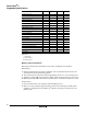
Suggested Specifications
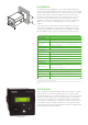
Table Values:
– Not Applicable
X Standard Feature
O Optional Feature
Metering and Instrumentation
Metering and communication requirements for Power-Zone 4 switchgear are listed below.
Main Metering
A. Metering requirements that exceed the capabilities of the circuit breaker trip units shall use the
optional Powerlogic
®
Power Monitoring System.
B. Three metering current transformers shall be appropriately sized for use on the incoming section.
C. Separate low voltage HMI and circuit monitor display shall be mounted near the incoming section.
D. Optional input/output (I/O) and the Ethernet communications card shall be provided as necessary.
Communications
A. Internal communications in the switchgear shall be Modbus
®
protocol.
B. Where necessary, an Ethernet gateway shall be located near the switchgear assembly and be
capable of accepting inputs from the Micrologic
®
trip unit(s), Powerlogic circuit monitor(s), and
Modicon PLCs.
LSIG/ground fault trip – O X X
Ground fault alarm (no trip) – – X X
Ground fault trip and programming alarm – – O O
Adjustable rating plugs X X X X
LED – long–time pickup X X X X
LED – trip indication – X X X
Digital ammeter – X X X
Phase loading bar graph – X X X
Zone selective interlocking – X X X
Communications – O X X
LCD dot matrix display – – X X
Advanced user interface – – X X
Protective relay functions – – X X
Thermal imaging – – X X
Contact wear indication – – X X
Temperature indication – – X X
Incremental fine tuning of settings – – X X
Selective long-time delay bands – – X X
Power measurement – – X X
Waveform capture – – – X
Data logging – – – X
Functions Basic Type A Type P Type H