
Specifications


Switchboards
1199 ‡For prices refer to List Price Book K-7
K
Switchboards
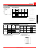
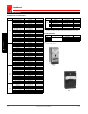
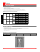
60-400 Main Cell
Dimensional Information
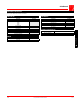
Main Cell Dimensions (in)
Amps Main Device W D ww
1600
CPH, PE, PX
36 24 24
Bolt Loc
2000
CPH, PE, PX
Bolt Loc
2500
PE, PX 36
24 36
Bolt Loc 42
3000
Masterpact
42 36 36
Bolt Loc
4000
Masterpact
48 48 36
Power Lok
5000 Masterpact 48 54/60 42
6000 Masterpact 54 60 42
Height includes channel base
Bus Stub (Back View)
Notes:
1. For 6”, X = 7.25; 8” wall, X = 9.25”;
12” wall, X = 13.25”.
If other than standard is required,
please consult factory.
2. Y dimensions and hole pattern as per
local hydro requirements.
3. Z = Main cell width - 2.5”.
60-400 Distribution Cell
Notes:
1. 4000A/5000A/6000A Copper Bus Only.
2. Wireway required for free-standing distribution.
Consult factory if deeper cell is more suitable than wireway.
3. Select branch breakers from pages K-12 to 16.
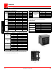
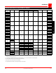
Distribution Cell Dimensions
Notes:
1. Using a 1200A QMQB in the distribution section takes up additional X space. If top
exit, remaining space is 52X. If bottom exit, remaining space is 34X. Only one
1200A QMQB per distribution section.
2. Some utilities may limit available MQS height to 70X.
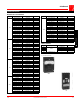
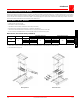
60-400
Distribution
Single Line
Diagram
To line up with main Wireway Adder
2
Branch Device Main Bus Amps List Price
MCCB
Fusible Switches
Sub-metering MQS
1600A
2000A
2500A
3000A
4000A
1
5000A
1
Consult Factory
6000A Consult Factory
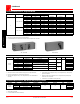
Branch Device Device Types
Width
(W)
Depth
(D)
Available
Device Height
MCCB
FK, CE, CJL,
CMH, TH1,
TH4, TH8, CK
42"
24"
104X36"
48"
Fusible
Switches
30-1200A
QMQB
42"
24"
106X36"
48"
MQS
30-200A
MQS
48"
24"
98X
2
36"
48"