
Specifications


14
© 2005 Schneider Electric All Rights Reserved 11/2005
Power-Zone
®
4
General and Application Information
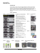
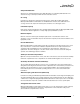
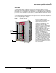
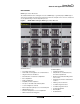
The examples below depict a typical Power-Zone 4 switchgear assembly.
Removable hinged
rear door with latches
(not shown; optional)
Removable
top plate
Removable
side panel
(not shown)
Auxiliary instrument
compartments
Circuit breaker
compartments
Removable
bottom plat
e
(optional)
Pilot Lights
(optional)
Standard ANSI #49
gray corrosion resistant
finish
Quarter turn
door latches
Hinged doors
Through-the-
door circuit
breaker access
Family of
Micrologic
®
trip
units
Wiring trough
Powerlogic
®
circuit
monitor display
(optional)
Switchgear (Rear View)
Switchgear (Front View)