www.mgeups.
34008236EN/AA - Page 2
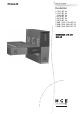
Introduction Thank you for selecting an MGE UPS SYSTEMS product to protect your electrical equipment. The Evolution range has been designed with the utmost care. We recommend that you take the time to read this manual to take full advantage of the many features of your UPS (Uninterruptible Power System). Before installing Evolution, please read the booklet presenting the safety instructions. Then follow the indications in this manual.
Introduction Pictograms Important instructions that must always be followed. Information, advice, help. Visual indication. Action. Audio signal.
Contents 1. 2. 3. 4. 5. 6. Presentation 1.1 Standard positions ...................................................................................................................... 6 1.2 Tower position ................................................................................................................................ 6 Rack position ................................................................................................................................. 6 Rear panels.............
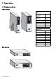
1. Presentation 1.1 Standard positions Tower position Dimensions (W x H x D) in mm S 1250 RT 2U S 1750 RT 2U 2000 RT 2U 440 x 86 x 509 S 2500 RT 2U S 3000 RT 2U 440 x 86 x 634 S 3000 RT 3U 440 x 131 x 484 S EXB 1250/1750 RT 2U 440 x 86 x 509 S EXB 2500/3000 RT 2U 440 x 86 x 634 S EXB 2500/3000 RT 3U 440 x 131 x 484 Weights in kg Rack position D H W 34008236EN/AA - Page 6 S 1250 RT 2U 24.3 S 1750 RT 2U 26.6 2000 RT 2U 25.7 S 2500 RT 2U 33.8 S 3000 RT 2U 33.8 S 3000 RT 3U 34.
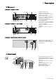
1. Presentation 1.
2. Installation 2.
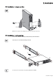
2. Installation 2.2 Installation in tower position 1 1 2 3 Note. The two supports for the upright position are used on the RT 2U version only. 2.3 Installation in rack position It is advised to first install the battery module, then the power module above. Follow steps 1 to 4 for module mounting on the rails. 1 1 3 1 2 1 4 2 4 The rails and necessary hardware are supplied by MGE UPS SYSTEMS.
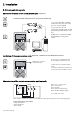
2. Installation 2.4 Communication ports Connection of RS232 or USB communication port (optional) The RS232 and USB communication ports cannot operate simultaneously. 1 - Connect the RS232 (33) or USB (34) communication cable to the serial or USB port on the computer equipment. 34 2 - Connect the other end of the communication cable (33) or (34) to the USB (1) or RS232 (2) communication port on the UPS. 33 The UPS can now communicate with MGE UPS SYSTEMS power management software.
2. Installation 2.5 Connection with a FlexPDU (Power Distribution Unit) module (optional) 1 - Evolution S 2500 / S 3000: connect the UPS input socket (10) to the AC-power source using the cable (31) supplied. Evolution S 1250 / S 1750 / 2000: use the power cable of the protected equipment. 8 Evolution S 2500 / S 3000 7 9 10 31 41 2 - Evolution S 2500 / S 3000: connect the input socket on the FlexPDU module (48) to the UPS outlet (7) using the cable (41) supplied.
2. Installation 51 The HotSwap MBP module has a rotary switch (53) with two positions: Normal - the load is supplied by the UPS, Bypass - the load is supplied directly by the AC-power source. BY PASS SWITCH Normal UPS ON OK to switch By-pass HotSwap MBP module operation 52 53 UPS start-up with the HotSwap MBP module 1 - Check that the UPS is correctly connected to the HotSwap MBP module. 2 - Set switch (53) to Normal position.
3. Operation 3.1 Start-up and normal operation 1 2 21 Press button (24) for approximately 1 second. The buzzer beeps once and all the LEDs go ON simultaneously. ◗ If AC input power is available, button (24) and LED (25) are ON. The load is supplied by the AC-power source. Conditions permitting, the UPS runs a battery test, indicated by LEDs (21) and the buzzer. ◗ If AC input power is not available, button (24) and LEDs (25) and (26) are ON. The load is supplied by the UPS on battery power.
3. Operation End of battery backup time ◗ ◗ All the LEDs go OFF. The audio alarms stops. The UPS is completely shut down. 3.3 Return of AC input power Following an outage, the UPS restarts automatically when AC input power returns (unless the restart function has been disabled via UPS personalisation) and the load is again supplied. 3.4 UPS shutdown 1 Press button (24) for approximately 2 seconds. 2 The devices connected to the UPS are no longer supplied. 24 3.
3. Operation 5 ROO Contact open: UPS shutdown Contact closed: UPS start-up (UPS connected to AC power and AC power is available) Note. The local ON/OFF control using button (24) overrides the remote-control function. 5 RPO Contact open: UPS shutdown, LED (26) goes ON To return to normal operation, deactivate the remote external contact (LED (26) goes OFF) and restart the UPS by pressing button (24). 4 - Plug connector (5) into the back of the UPS.
4. Personalisation using external software Insert the Solution-Pac CD-ROM in the drive. On the first navigation screen, select "Point to Point solution" and follow the instructions on how to install the Personal Solution-Pac software. ◗ Then select "Settings", "Advanced settings" and "UPS settings". Note that the Linux/Unix/MacOS versions of Personal Solution-Pac software do not offer this possibility.
5. Maintenance 5.1 Troubleshooting Indication Diagnostic Correction 1 When the UPS is started using button (24), all the LEDs go ON once and the buzzer beeps once, then LED (26) remains ON. The remote power off (RPO) contact has been activated to shut down the UPS and now prevents restart. Set the contact back to its normal position and press button (24) to restart. 2 Button (24) and LEDs (25) and (26) are ON and all the LEDs on bargraph (20) flash.
5. Maintenance 5.2 Battery-module replacement Safety recommendations The battery can cause electrocution and high short-circuit currents. The following safety precautions are required before servicing the battery components: ◗ Remove watches, rings, bracelets and all other metal objects from the hands and arms, ◗ Use tools with an insulated handle. Battery-module removal A - Unscrew the left-hand side of the front panel (two screws). B - Remove the part.
5. Maintenance Mounting the new battery module Carry out the above instructions in reverse order. ◗ To ensure safety and high performance, use only batteries supplied by MGE UPS SYSTEMS. care to firmly press together the two parts of the connector during remounting. ◗ Take 5.
6. Appendices 6.1 Technical specifications Filter Transformer (AVR) Charger Inverter Battery Output power Evolution S 1250 Evolution S 1750 Evolution 2000 Evolution S 2500 Evolution S 3000 1250VA/1150W 1750VA/1600W 2000VA/1600W 2500VA/2250W 3000VA/2700W AC input power ◗ Rated input voltage ◗ Input-voltage range ◗ Input-frequency range Single phase 220~240 V 160 V to 294 V (1) 47 to 70 Hz (50 Hz system), 56.
6. Appendices 6.2 Glossary Backup time Time during which the load can be supplied by the UPS operating on battery power. Battery test Internal UPS test to check battery status. Booster mode Automatic UPS mode that steps up the AC voltage if it is too low, to a level above the personalised set-point, without discharging the battery. Bypass AC input Bypass line from the AC-power source, controlled by the UPS, used to directly supply the load if an overload or a malfunction occurs on the UPS.
e-mail: info@direktronik.