www.mgeups.
Page 2 - 34020201EN/AB
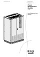
Introduction Thank you for selecting an MGE UPS SYSTEMS product to protect your electrical equipment. The Power Management Module (PMM) has been designed with the utmost care. We recommend that you take the time to read this manual to take full advantage of the many features of your new equipment. MGE UPS SYSTEMS pays great attention to the environmental impact of its products.
Foreword Structure of this document Information may be found via: ◗ the contents, ◗ the index.
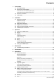
Contents 1. Presentation 1.1 250 A PMM modules .................................................................................................................... 6 1.2 Access to the circuit breakers ................................................................................................... 7 Version with 126 circuit breakers (doors open) ............................................................................... 7 Version with 60 circuit breakers (doors open) ..............................
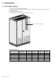
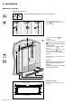
1. Presentation 1.1 250 A PMM modules You can choose from 6 different modules depending on: ◗ the number of output circuits required and the type of protection (126 standard circuit breakers or 60 circuit breakers with earth-leakage protection), ◗ the presence of an isolation transformer, ◗ the depth (825 with or without an isolation transformer and 425 without).
1. Presentation 1.
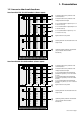
1. Presentation 1.3 Access to connections Remove the eight cover panels (each secured with two screws).
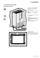
2. Installation 2.1 Setting up the module Module 825 mm deep 1. Install the lower base panels 23 on the sides that will not be accessible (not mandatory). 2. Position the module. 3. Level the module using the adjustable feet 24 . 4. Install the lower base panels 23 on the visible sides. ≥400 mm Connection cables run under the false floor or in a cable trough. Important. At least 400 mm of free space is required above the module to ensure correct ventilation.
2. Installation Module 425 mm deep Installation against a wall Caution: during handling, make sure the module does not fall over. 1. Turn to horizontal position the two brackets 25 at the back used to secure the module (see figure). 25 26 ≥ 400 mm 1250 1685,5 2. Install the rear base panel 23 (not mandatory). 3. Position the module. 4. Level the module using the adjustable feet 24 . 5. Attach the module to the wall using the two rear brackets. 6. Install the base panels 23 on the sides and front. 7.
2. Installation Back-to-back assembly Caution: during handling, make sure the modules do not fall over. 1. Remove the brackets 25 on the back of the module (used only for securing the module to a wall) and retighten the fixing screws. 25 25 2. Position the modules and use the brackets 26 on the top to interconnect the two modules (see figure). 26 3. Level the modules using the adjustable feet 24 . 4. Install the base panels 23 on the sides and fronts.
2. Installation 2.2 Input power connections Specifications for protection devices and cables are provided in section 6 (Appendices, technical data sheet). To access the connections, see section 1.3. Connection cables are not supplied. Module with isolation transformer Q1 1. Connect the PE or PEN protection cable to the earthing bar at the bottom of the module. 2. Remove the bottom cover on circuit breaker Q1. 3.
2. Installation Module without isolation transformer, combined earth and neutral (TNC system) Q2 1. Connect the PEN protection cable to the earthing bar at the bottom of the module. 2. Remove the bottom cover on circuit breaker Q2. 3. Connect the three phases of the input power cable to the bottom terminals of circuit breaker Q2 (without removing the control wires that are already connected). 4.
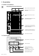
2. Installation 2.3 Output circuit connections It is advised to use crimped ferrules on the phase wires and lugs on the earth wires. 1. Connect the earth wire of each output cable to the earth connection bar located to the left of the metal trunking. 2. Connect the phase and neutral wires to each circuit breaker. 3. Tie the cables to the metal trunking. Note: it is advised to make the connections from the top down. Ph 2 1 N Q2 2 3 Q1 2.4 Alarm and remote shutdown connections 1.
2. Installation 2.5 Communication connections RS-485 RS-232 1. Connect the communication cable to the RS232 or RS485 connector on the righthand door of the module. 2. Run the cable as shown in the figure opposite. 3. Tie the cable down to the module frame.
3. Operation 3.1 Turning on the PMM module 1. Close the upstream switching device (external and not supplied) on the circuit supplying the PMM module. 2. In a module with an isolation transformer, close ("I" or ON position) circuit breaker Q1 5 (see page 7) . 3. Make sure disconnector-fuses F1 and F2 are closed and close ("I" or ON position) circuit breaker Q2 5 (see page 7) . ◗ The system status LED 17 (see page 8) flashes yellow a few seconds, then green and should subsequently remain green.
3. Operation 3.3 Metering Output-circuit metering Ph-A: measurements on phase A CH-01: measurements on output circuit 01 Ph-A BCM CH01 CH02 0.000 0.000 Display of the current drawn by the output circuit in amperes General metering GENE: general measurements. GENE MCM KWH 0000.0 KW 0000.0 Measurement units: KWH: total energy consumed by the PMM module in kWh. This value can be reset via the communication function. KW: total active power drawn by the PMM module in kW.
3. Operation 3.5 Setup Access setup mode by pressing simultaneously the SELECT DOWN DOWN SELECT UP UP UP + DOWN buttons and then entering the password: . This mode presents the functions listed below. View System Info, Find Meters and Review Meters : these functions are reserved for MGE UPS SYSTEMS. Setup Communication : access to the communication settings.
4. Maintenance 4.1 Trouble-shooting and solutions Alarm Meaning Action WARNING The current on the indicated output circuit is between 60 and 80% of the maximum value for the circuit. Monitor the power drawn on the circuit and avoid adding other loads to the circuit. ALARM The current on the indicated output circuit is higher than 80% of the maximum value for the circuit. Turn off certain loads connected to the circuit until the fault disappears (after alarm reset).
5. Environment This product has been designed to respect the environment. It does not contain CFCs or HCFCs. Recycling at the end of service life MGE UPS SYSTEMS undertakes to have all products recovered at the end of their service life recycled by certified companies in compliance with applicable regulations (contact your branch office). Packing materials Comply with all applicable regulations for recycling of packing materials. Web Site: www.mgeups.
6. Appendices 6.1 Technical data sheets Electrical characteristics Rated input current: Rated output current: Input voltages: ◗ Rated voltage: ◗ Maximum voltage: ◗ Minimum voltage: ◗ Rated frequency: Output voltages: F1 and F2 fuses: 250 A per phase and 400 A for the neutral 16 A per phase 380 V / 400 V / 415 V 457 V (415 V +10%) 342 V (380 V -10%) 50 or 60 Hz (47 Hz minimum, 63 Hz maximum) 220 V / 230 V / 240 V 0.
6. Appendices 6.
6. Appendices 6.3 Auxiliary contact functions Alarm LED 17 Type 1-alarm contact Type 2-alarm contact Cause Normal operation Green OFF OFF Downgraded operation Yellow ON OFF Current on at least one output circuit between 60% and 80% of max. value for the circuit. Overload or overvoltage Red ON OFF ◗ Other fault Red OFF ON ◗ Current on at least one output circuit higher than 80% of max. value for the circuit, ◗ or overvoltage (> 457 V), ◗ or overcurrent (> 250 A).
6. Appendices Cards BCM1, BCM2 and BCM3 (status and measurements for 42 or 21 output circuits of one phase) All the variables are whole numbers. # 1 2 ... ... 41 42 Bit 43 R/W R R ... ...
6.
6.
6.
6.
6. Appendices # Bit 268 269 270 271 272 R/W W W W W W 273 to 280 281 R R 0 1 2 3 4 5 6 7 8 9 10 11 12 13 14 15 283 R 0 1 2 3 4 5 6 7 8 9 10 to 15 284 R 0 1 2 3 4 5 6 7 8 9 10 11 Description Global circuit breaker rating Global minor alarm threshold (%) Global major alarm threshold (%) Global minor alarm time delay Global major alarm time delay A value entered in the global parameters to enable the 42 (or 21) output circuits to be set to that value at the same time.
6.
6. Appendices Card MCM (general status and measurements) The variables entered in registers 1 to 74 are whole numbers read on 16 bits. The variables entered in registers 1 to 29 are also accessible in “floating” format on 32 bits (registers 257 to 314 in the “Float.” column of the table). The “floating” variables are read only. Multiply each value in whole number format by the coefficient indicated in the “Coeff.” column of the table. # Bit Float.
6. Appendices 6.5 Glossary ALARM Major alarm signalling that the current in the output circuit considered is higher than 80% of its rated value. AUX ALARM INPUT Alarm indicating either: ◗ excessive temperature rise in the isolation transformer, ◗ actuation of the remote shutdown function. DOWN Scroll button used to access previous measurement (metering mode) or setting (setup mode).
6. Appendices 6.5 Index A H Alarms Displayed .......................................................... 17, 19 Remote ............................................................. 19, 22 Heat losses .................................................................... 21 I Isolation transformer .................................................. 6, 22 C Cable sizes .................................................................... 21 Characteristics Electrical ..........................................
Page 34 - 34020201EN/AB