Always “On” UPS Systems Inc. GES L-Series – Single Phase Input, Single Phase Output Uninterruptible Power Supply USER MANUAL Version 1.
Always “On” UPS Systems Inc.
Always “On” UPS Systems Inc. SAVE THESE INSTRUCTIONS − − − − − − This manual contains important instructions for the GES-801L, GES-102L, GES-152L, GES-202L, GES-302L and should be followed during installation and maintenance of the UPS and batteries. The UPS contains voltages that are potentially hazardous. Please contact our dealers or qualified personnel for service. Servicing of the batteries should be performed or supervised by personnel knowledgeable with batteries and the required precautions.
Always “On” UPS Systems Inc. TABLE OF CONTENTS INTRODUCTION ........................................................................................................................................ 5 SAFETY INSTRUCTIONS ......................................................................................................................... 6 PRESENTATION ........................................................................................................................................ 7 FRONT PANEL .....
Always “On” UPS Systems Inc. Introduction The L-Series is a Line Interactive UPS system that includes the newest and latest technology enhancements. The Line Interactive technology with AVR function (online voltage boost-up & buck-down) allows for a wide input voltage range of 90 to 150VAC. The L-Series UPS is the ideal protection for microprocessor controlled loads. With the utility power connected, the charger begins to operate immediately, charging the battery.
Always “On” UPS Systems Inc. Safety Instructions The UPS has its own internal energy source (batteries), therefore the output receptacles may have electricity present even though the UPS is disconnected from the utility power. The DC voltage provided from the internal batteries are as follows: a) GES-801L 24VDC d) GES-202L 48VDC b) GES-102L 24VDC e) GES-302L 48VDC c) GES-152L 36VDC Isolated Ground Wire refers to the bare wire connecting electrical equipment to ground.
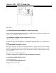
Always “On” UPS Systems Inc. Presentation Front Panel 1. POWER bar graph (BATTERY CHARGE/LINE VOLTAGE) This displays the present battery charge as a percentage of battery capacity. It also displays the utility line voltage. 2. LOAD bar graph This displays the amount of power required by the load as a percentage. 3. "OVERLOAD" indicator (RED LED) This LED lights when the load(s) connected to the UPS exceed the UPS's capacity. See Section 6.3 for solution to this problem. 4.
Always “On” UPS Systems Inc. Rear Panel 11. TELEPHONE/MODEM/ETHERNET SURGE PROTECTION Surge protection for telephone line, modem line, and 10BaseT line to maintain a completely safe connection for INTERNET/INTRANET service. 12. EXTERNAL BATTERY PACK CONNECTOR (optional) Allows for extended runtime. Caution: Use only factory supplied or authorized connecting cable for external battery pack! 13.
Always “On” UPS Systems Inc. 16. INPUT CIRCUIT BREAKER It trips when the connected loads exceed the protected receptacle's capacity. The center plungers of the circuit breakers extend when tripped. 17. SITE WIRING FAULT INDICATORS (RED LED) It illuminates when the UPS is connected to an improperly wired AC power outlet. Note: This device is available on 120 VAC model only. 18. COMPUTER INTERFACE Provides both RS-232 and relay signal to support NOVELL, UNIX, DOS, WINDOWS and other operating systems.
Always “On” UPS Systems Inc. Installation Unpacking and Inspection Examine the packaging for damage. Inform the carrier immediately if and/or when damage is noticed. Retain the packaging for future use. Placement Install the UPS in a protected area with adequate airflow and free of excessive dust. Do not operate the UPS where the temperature and humidity is outside the specified limits. Connect Computer Interface (optional) UPSilon 2000 (or selected option) and an interface kit can be used with this UPS.
Always “On” UPS Systems Inc. Connecting the Telephone/Modem/Ethernet Lines Connect a telephone line, modem line, or 10BaseT line into the telephone/modem/Ethernet surge protection sockets on the back of the UPS. The RJ-45/RJ-11 modular sockets accept standard single line telephone connections and 10BaseT connectors. This connection will require another length cable. Note: This connection is optional. It is not necessary to use this with the UPS.
Always “On” UPS Systems Inc. Operation Switching “On” the UPS With the UPS plugged in, press and hold the “ON/TEST” button for at least 1 second to switch the UPS on. The UPS will perform a self-test each time it is switched on. Note: When switched off, and still plugged into utility, the UPS maintains the battery charge and will respond to commands received through the computer interface port. Switching “Off” the UPS Press and hold the “OFF” button until the "LINE NORMAL" or "BACK UP" LED turns off.
Always “On” UPS Systems Inc. Battery Charge Bar Graph This 5 LED display indicates the present charge of the UPS's batteries as a percentage of the total battery capacity. When all five LED’s are lit, the batteries are fully charged. When only two of the LED’s are lit, the batteries can supply less than two minutes of power to the load. Cold Start When the UPS is off, and there is no utility power, use the cold start feature to apply power to the loads from the UPS's battery.
Always “On” UPS Systems Inc. Software Options UPSilon 2000 Software The UPSilon 2000 software utilizes standard RS-232 interface to perform monitoring functions, and provides an orderly shutdown of a computer system in the event of power failure. Moreover, UPSilon 2000 displays all the diagnostic symptoms through a graphical interface, such as Voltage, Frequency, Battery Level, etc. The software is available for DOS, Windows 3.x, Windows 95/98/00 & Windows NT V3.5 or later, FreeBSD, Linex, Novell and more.
Always “On” UPS Systems Inc. Computer Interface Port The computer interface port has the following characteristics: The communication port on the back of the UPS may be connected to a host computer. This port allows the computer to monitor the status of the UPS and control the operation of the UPS. Its major functions include the following: 1. 2. 3. 4. The ability to broadcast a warning when the power fails. The ability to close any open files before the battery reserves are exhausted.
Always “On” UPS Systems Inc. Battery Replacement Your batteries should run anywhere from 3-5 years before they need to be replaced. Please follow the instructions below for easy, trouble free, battery replacement. 1. 2. 3. 4. Turn the UPS off (follow procedure previously mentioned) Unplug the UPS from utility power source and disconnect all connected loads. Disconnect AC power cord from unit. Using a phillips screw driver, unscrew the screws holding the top of the unit to the bottom.
Always “On” UPS Systems Inc. Troubleshooting Please follow the guidelines below for solutions to common problems: Check UPS input plug and wiring. Check UPS input voltage. Please prepare the information as follows for service personnel: UPS model number and serial number Description of problem(s) in detail.
Always “On” UPS Systems Inc. Storage Storage Conditions Store the UPS covered and upright in a cool, dry location, with its battery fully charged. Before storing, charge the UPS for at least eight (8) hours. Remove any accessories from the accessory slot and disconnect any cables connected to the computer interface port to avoid unnecessary drain on the battery.
Always “On” UPS Systems Inc. Battery Bank Installation Install up to 8 battery banks per L Series UPS following the instructions below. 1 2 3 4 BLACK RED Caution: Make sure the UPS is shutdown and unplugged before connecting additional Battery Packs (refer to Switching the UPS “Off” section, page 11) 1. 2. 3. 4. Locate the external battery connector located at the rear of the UPS. Make sure you are connecting the connector correctly or problems will occur.
Always “On” UPS Systems Inc. Specifications Specification Comparison GENERAL MODEL NO. MAXIMUM CAPACITY UPC ORDER CODE GES-801L GES-102L 800VA / 560W 825433 22100 1kVA / 700W 825433 22200 VOLTAGE RANGE FREQUENCY RANGE NOMINAL VOLTAGE AUTO VOLTAGE REGULATION CURRENT 6.6A FREQUENCY OUTPUT POWER FACTOR WAVE FORM (ON BATTERY) LOAD CREST FACTOR TRANSFER TIME OUTLETS 4 BATTERY TYPE BATTERY QUANTITY VOLTAGE 2 24VDC RECHARGE TIME FULL LOAD BACKUP POWER TIME HALF LOAD PENTIUM & 17" MON GES-202L 1.
Always “On” UPS Systems Inc.
Always “On” UPS Systems Inc. CONTACT INFORMATION Additional Purchases or Upgrades Always “On” UPS Systems Inc. Bldg 1 – 150 Campion Road, Kelowna, BC, Canada, V1X 7S8 Phone: (250) 491-9777 Ext 451 Fax: (250) 491-9775 Email: sales@alwaysonups.com Website: www.alwaysonups.com QA / Warranty Questions Always “On” UPS Systems Inc. Bldg 1 – 150 Campion Road, Kelowna, BC, Canada, V1X 7S8 Phone: (250) 491-9777 Ext 209 Fax: (250) 491-9775 Email: qa@alwaysonups.com Website: www.alwaysonups.