MODERN HOME PRODUCTS GAS GRILLS Owners Manual Assembly and Maintenance Instructions For models JNR, WNK and TJK Series THIS GAS APPLIANCE IS DESIGNED FOR OUTDOOR USE ONLY. FOR YOUR SAFETY If you smell gas: 1. Shut off gas to appliance. 2. Extinguish any open flame. 3. Open Lid. 4. If odor continues, immediately call your gas supplier or your fire department. FOR YOUR SAFETY 1. Do not store or use gasoline or other flammable vapors and liquids in the vicinity of this or any other appliance. 2.
Safety DANGER Failure to follow the Dangers, Warnings and Cautions contained in this Owner’s Manual may result in serious bodily injury or death, or in a fire or an explosion causing damage to property. WARNINGS Do not store a spare or disconnected liquid propane cylinder under or near the barbecue. Improper assembly may be dangerous. Please carefully follow the assembly instructions in this manual.
Contents TABLE OF CONTENTS Safety (Dangers & Warnings)……………. 2 Warranty……………………………………... 4 General Instructions………………………. 5 Mountings……………………………………. 6 -13 Cart……………………………………………….. 6 -7 Deck/Patio……………………………………….. 7-9 In-Ground………………………………………… 9 Optimum Console………………………………. 10 -11 Built-In……………………………………………. 12 -13 JNR/WNK Grill Assembly…………………. 14 -18 TJK Grill Assembly…………………………. 19 - 20 Gas & LP Tank Connections……………… 21 - 22 Leak Testing & Lighting The Grill……….. 23 Maintenance………………………………….
Warranty ————————————————————— MODERN HOME PRODUCTS —————————————————————– LIMITED WARRANTY Modern Home Products Corp. Offers to the original purchaser a Limited Warranty on all aluminum grill components except the 7 year “SearMagic” cooking system. These components will be free from defects in material and workmanship (excluding paint) when subject to normal domestic use and service.
General Instructions GENERAL INSTRUCTIONS STORAGE This installation guide provides you with easy to follow illustrations and instructions to assemble your MHP Gas Barbecue Grill. Turn gas OFF at the LP cylinder (or at the shut OFF valve in the case of Natural Gas) when the MHP Gas Barbecue Grill is not in use. Before you start assembling and using your MHP Gas Barbecue Grill we recommend that you read through all precautions, safe guards and instructions to avoid any personal injury or property damage.
Mountings Step 1: Leg Assembly (Fig. 2) Cart Assembly Instructions (JCP, JCN, WCP & WCN) 1. Tip the grill head bottom on end as shown in Fig. 2. (TIP: work on protected area such as: carpet, tarp or one of the boxes to protect cart finish.) 2. Attach the two short legs to the left end of the grill head bottom with the “Hose Ring Hole” leg facing grill front. Use two ¼-20 x 1½" slotted bolts for each leg. Insert bolts from inside grill box, attach leg and fasten with ¼-20 Kep nuts. 3.
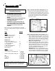
Mountings For Natural Gas Models (Note: Tank Holder Ring is not included with natural gas models.) Fig. 3 If the grill is to use natural gas from the supplied 12foot hose: the hose must pass through the hose clamp (See Fig. 1). The hose will have a quickdisconnect fitting at the source and the source will have a gas shut off valve with easy access. When you have completed the mount assembly go to the appropriate Grill Assembly Section and assemble the grill head.
Mountings 3. Secure the gas line with the tube clip. (Option: On a raised deck if the gas supply line is to be run straight up into the post from below use the tube clip to attach the gas line to the deck for support. 4. At the access door connect a 3/8" flare coupling (not supplied by MHP) to the gas supply line and Stainless Steel tubing. Position the tubing in the top notch of the post. Bend the tubing at the top end to match the Feed Line of the grill valve. Do not kink the tubing.
Mountings cement (gravel) up to the gas line access hole. Keep in mind that the gas line access hole is on the back of the post and the notch at the top if facing front. Recheck plumb and allow cement to set. 3. Mount the grease cup holder to the rear flange hole with a ¼ - 20 x ¾" bolt and ¼-20 Kep nut. The grease cup holder is supplied with the grill head. 2. Run the gas supply line into the post access hole (just above the cement). Make a 90° bend to reach the access door opening.
Mountings Stainless Steel Optimum Console Assembly Instructions • • • • The JNR, WNK or TJK model grills may be mounted on the Optimum Console. The gas supply may be either LP or Natural. The grill head should not be attached to the Optimum Console until the console is completely assembled The Optimum Console comes in two cartons—Box A contains the console and all associated hardware. Box B contains either the pedestal or cart base and all base hardware. Step 1: Connect the Tank Locking Bar (Fig. 10) 1.
Mountings OPTION: For OPTIMUM Cart Only: (Fig. 12) Step 4: Attaching the Access Panel (Fig. 14) 1. Attach the wheels by slipping the axle through the base, slide the wheels on and secure with the axle clips. Finish by snapping the hub caps on before standing unit upright. Note: Do not attach the front access panel until the control panel has been attached to the grill head bottom and the gas supply line has been properly connected and leak tested. 1.
Mountings Complete View Of Built-In Built-in Kit Mounting Assembly Instructions (NMS) • The JNR, WNK or TJK model grills may be mounted as a built-in. • For use with natural or hard–plumbed propane gas. • Use of the Built-in kit for LPG poses a safety risk and voids any and all warranty. • Enclosure must be constructed from non combustible materials. • The Built-In kit and grill head connection will be assembled upside down. • Refer to appropriate section for grill head assembly.
Mountings Step 2: Built-In Mounting Assembly Note: Be certain that the gas pressure is between 6.5" and 7.5" water column. Excess gas pressure can cause warping and damage to grill head. 6. When finished connecting gas supply, slide grill all the way into to opening so that the “L” bracket face flanges fit snuggly to your enclosure face. Drill a hole in the masonry to match up with the “L” bracket face flange holes and fasten with lag bolts (not supplied).
JNR & WNK Assembly Instructions CARTON CONTENTS Please check to be sure that all parts are included before proceeding with assembly. Contact your local dealer if any parts are missing. Note: The grill is partially assembled. The Burner, Spider Guards, Venturis, Ignitor Collector Box are installed. Also, for LP units the Gaslow Regulator and Hose are installed.
JNR & WNK Assembly Instructions Grill Head Assembly Instructions • • • • • The grill head bottom must be attached to the mounting before starting. It is easiest to work with the grill in the upright position. The difference between the JNR and the WNK is the WNK is larger, has two side shelves and the warming rack fastens differently. Leak test all gas connections before using. Caution: Combustible material should never be within 24 inches of the top, bottom, back or sides of your MHP Gas Barbecue Grill.
JNR & WNK Assembly Instructions C. Ignitor Wire Connection (Fig. 21) Step 2: Connect the gas supply line (Fig. 23) 1. Tip the grill on its back (or upside down) and attach the control panel ignitor wire to the terminal sticking out from the bottom of the grill. Be careful not to crack the delicate porcelain insulator. A. For LP-Gas Tank and LP Cart Models: 1. Pass the Gaslow Regulator Hose through the hose clamp ring and screw the ring to the front of the left leg. 2.
JNR & WNK Assembly Instructions Step 2: Continued Natural gas hose for Optimum cart mount: D. Optimum Console Mount Gas Connections The natural gas cart uses a 12 foot hose with a quick disconnect (supplied). The hose passes beneath the heat shield through the front access opening and connects directly to the control valve. The quick disconnect end attaches to the gas supply line at the shut-off valve. (Fig.
JNR & WNK Assembly Instructions Step 4: Attaching the Grill Lid (Fig. 30) 1. Attach the grill lid to the grill head bottom using the two Hinge Pins and Hinge Clips. Step 7: Warming Rack Step 5: Connect the Handle (Fig. 31) 1. Attach the handle to the grill lid using two ¼ - 20 x 1 ½" Hex bolts with Kep nuts. Graphite Gaskets are positioned between the end caps and grill lid as shown in fig. 31. Use two 7/16" wrenches, one to hold the bolt head and one to tighten the nut. 1.
TJK Assembly Instructions CARTON CONTENTS Please check to be sure that all parts are included before proceeding with assembly. Contact your local dealer if any parts are missing. Note: The grill is partially assembled. The Burner, Spider Guards, Venturis, Ignitor Collector Box and the Stainless Steel Handle are installed. Also, for LP units the Gaslow Regulator and Hose are installed.
TJK Assembly Instructions Grill Head Assembly Instructions • • • • The grill head bottom must be attached to the mount before starting. It is easiest to work with the grill in the upright position. Leak test all gas connections before using. Caution: Combustible material should never be within 24 inches of the top, bottom, back or sides of your MHP Gas Barbecue Grill. Complete View of TJK Grill Step 4: Attaching the Grill Lid (See JNR/WNK instructions on page 18, Fig 30.
Gas & LP Tank Connections LP Gas Cylinder Requirements: (The LP-Gas Cylinder is not supplied with your MHP Grill.) • The LP cylinder should be equipped with an OPD (Overflow Prevention Device) and a QCC! Or Type 1 (CGA810) cylinder connection. This cylinder connection is compatible with the grill connection. OPD is an internal mechanical device that limits the amount of liquid propane and prevents overfilling the LP cylinder.
Gas& LP Tank Connections LP-GAS CYLINDER FILLING & HANDLING (Continued) • Air must be removed from a new LP cylinder before the initial filling. Your LP dealer is equipped to do this. • The cylinder supply system must be arranged for vapor withdrawal • Always keep and store cylinders in an upright, secure position. • Use this grill outdoors in a well-ventilated area. Do not use in a garage, building, or any other enclosed area.
Leak Testing & Lighting Grill Leak Testing Lighting Your Grill LEAK TEST ALL GAS CONNECTIONS BEFORE USING YOUR GRILL. ALWAYS OPEN GRILL BEFORE LIGHTING THE BURNER. DO NOT SMOKE WHILE LEAK TESTING. DO NOT LEAN OVER AN OPEN GRILL. KEEP YOUR HEAD AND BODY AT LEAST ONE FOOT AWAY WHEN LIGHTING THE GRILL. DO NOT LEAK TEST WITH A MATCH OR OPEN FLAME. IF BURNER DOES NOT LIGHT, IMMEDIATELY TURN BURNER CONTROL KNOBS TO OFF. WAIT FIVE MINUTES TO LET GAS CLEAR BEFORE YOU TRY LIGHTING AGAIN.
Warning: Check the hose before each use of the grill for nicks, Maintenance cracking, abrasions or cuts. If the hose is found to be damaged in any way, do not use the grill. Replace using only MHP authorized replacement hose. Annual Maintenance General Maintenance After a period of nonuse or to keep your grill in top operating condition, you should perform the following maintenance procedures to keep the grill ready for instant use and for your safety.
Maintenance B. Check spark. Pull the connector wire from the collector box (see “X” Fig. 46). Bring wire to bottom or top of control panel, hold about 1/8" away and operate the ignitor. Check for spark. If there is no spark replace the Rotary Ignitor. If there is a spark the Rotary Ignitor is OK, but the Collector Box/Electrode assembly should be replaced (the ceramic insulator could be cracked).
Maintenance & Tube Bending General Maintenance Sear Magic Grid System Care Stainless Steel Cleaning (TJK, Optimum Console) For best results, preheat the grill for 10 minutes. 1. Use a brass bristled brush to clean top rungs. 2. Use the supplied “Forked Grid Tool” to clean the valley areas between the main rungs. Simply run the tool back and forth with enough pressure to remove the debris. For heavy build-ups you can use a plastic scouring pads.
Troubleshooting Problem Yellow or orange flame and the smell of gas. Cause 1. 2. 3. Burner does not light or flame is low in HIGH position. 1. 2. 3. Blockage in the venturi tube or orifice. Orifice not seated properly in the venturi Tube. Bent or kinked hose. Check 1. 2. 3. Could be a kink in the gas supply 1. line. 2. LP tank could be low or empty. 3. LP regulator excess flow feature has been activated. Clean venturi (See section “Annual Maintenance”.
Parts Information Parts are divided below into lists associated with the three different grill configurations . When ordering a part please provide the grill Identification, part number, quantity and product description. To order contact your local MHP dealer or MHP’s customer service: phone: 1-888-647-4745, fax: 1-800-637-2918, or E-mail: mhp@voyager. net for the dealer nearest you.
Parts Information TJK LID AND UPPER SIDE SHELF PARTS IDENTIFICATION 29
Parts Information JNR and WNK Cart Mount (Nat. & LP) (JCP, JCN, WCP & WCN) Item 50 52 53 54 55 39 56 57 58 59 60 47 62 63 64 65 7 67 69 74 82 Qty.
Parts Information TJK and WNK Stainless Steel Optimum Console Mount (Nat. & LP) Item 84 85 86 87 82 87 88 89 90 91 92 93 94 95 41 54 58 62 63 67 69 Qty. 1 1 1 1 1 4 12 10 1 1 1 4 8 1 1 2 2 1 1 1 2 Description Stainless Steel Front Panel Cast Aluminum Base Stainless Steel Column Heat Shield Stainless Grease Cup ¼ - 20x1¼ S.S. Hex Head Bolt ¼ - 20 S.S. Kep Nuts ¼ - S.S. Flat Washers 6 “ Wheels (Cart Only) Axle (Cart Only) Tank Lock Bar Rectangular Washers ¼ - 20 x ¾” S.S. Hex Head Bolt 2-Piece Gasket 28” S.
Outdoor Creations From MHP™ 150 South Ram Road, Antioch, Illinois 60002 Toll-Free Tel: 1-888-647-4745 Fax: 1-800-637-2918 E-Mail: mhp@voyager.net Web Site: www.modernhomeproducts.com MHP Grills are covered by U.S. Patent Nos. D 326,207 and D 359,877; Burners by U.S. Patent Nos. 4,267,506; 4,373,505: 4,267,816: 4,488,534 MHP configuration, BBQer’s Choice, Sear Magic, Flavor Master, Duro-Cart and Infra-Roast are trademarks of Modern Home Products Corporation. ©2001 Modern Home Products Corporation.