GEMINI HSC GUIDE TO INSTALLATION SERVICE & CLEANING L 117
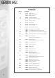
GEMINI HSC Index page 2 section 3 . . . . . . . . . . .1.0 2.0 3.0 General Notes Water Supply Regulations Building Regulations 4 . . . . . . . . . . .4.0 Specification for Gemini 5 . . . . . . . . . . .5.0 . . . . . . . . . . . .6.0 Single Calorifier Dimensional Data Connection Details 6 . . . . . . . . . . .7.0 Technical Data 7 . . . . . . . . . . .8.0 . . . . . . . . . . . .9.0 Installation Requirements System Schematics 8 . . . . . . . . . . .9.0 System Schematics (Contd) 9 . . . . . . . .
GEMINI HSC 1.0 general notes The Gemini HSC range of high performance calorifiers from MHS Boilers Ltd comprises six models, the 60-i, 100-i, 150-i, 200-i, 300-i and the 500-i providing hot water outputs of up to 1474 L/hr continuous at a temperature rise of 50°C. Gemini HSC calorifiers are constructed from two concentric cylindrical tanks (tank within a tank), a principle which provides many advantages over conventional coil or tube type calorifiers.
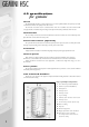
GEMINI HSC 4.0 specification for gemini vessel The Gemini HSC calorifier is constructed from two concentric cylindrical tanks. The primary outer tank is manufactured from boiler quality ST-37 carbon steel. The domestic hot water vessel is constructed from A1S1 316 Ti stainless steel and is formed with corrugated walls, and welded using inert Argon atmosphere followed by sand blast oxide removal.
GEMINI HSC 5.0 single calorifier dimensional data B a e b 60 E 40 60 - i 100 - i 150 - i 200 - i 300 - i 500 - i c 448 B a b e A E D c A 448 d d 207 G 60 G 60 F F Fig 1. Dimensions in millimetres Model A B D E F G 60 - i 749 480 – 210 145 31 100 - i 1154 480 – 205 145 31 150 - i 983 620 – 248 164 50 200 - i 1239 620 390 247 148 34 300 - i 1724 620 875 226 146 34 500 - i 1730 770 861 283 168 54 6.
GEMINI HSC 7.0 technical data HSC 60 - i 100 - i 150 - i 200 - i 300 - i 500 - i DHW Capacity L UK Gal 55 12.09 100 22.0 150 33.0 200 44.0 300 66.0 500 110.0 Primary Capacity L UK Gal 22 4.83 32 7.03 44 9.67 56 12.31 72 15.83 98 21.55 m2 ft2 0.6 6.45 1.0 10.76 1.2 12.91 1.6 17.22 2.4 25.83 3.1 33.
GEMINI HSC 8.0 installation requirements The calorifiers must be installed to comply with the Water Supply (Water Fittings) Regulations 1999, Building Regulations, I.E.E. Regulations and the Bye-Laws of the local Water Company. The installation should also be in accordance with any Local Authority requirements and the recommendations of CP342 Centralised hot water supply, or BS6700 as appropriate.
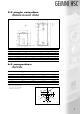
GEMINI HSC 9.0 system schematics (contd) typical multiple calorifiers open vented application Open Vent Secondary Pump IV NRV Cold Feed IV 3 Way Vent Valve Flow From Boiler IV IV Divertor Valve Reg Valve Drain at Low Level Return to Boiler Fig 5.
GEMINI HSC 10.0 unvented hot water installation To install a Gemini HSC Calorifier as an unvented hot water storage package, then a Water Regulations Advisory Scheme approved kit of safety devices, valves and fittings complying with BS7206:1990 and satisfying the requirements of Building Regulation G3, available from MHS Boilers Ltd must be installed to protect the system and prevent water temperature from exceeding 100°C. The kit of parts includes as a minimum (see checklist of components 10.
GEMINI HSC 10.1 component check list (contd) calorifier model 200i Component Part No. 1. 22mm pressure reducing valve with integral coaxial strainer and balanced cold water take off connection (blanked). Pre-set 3.5 bar. PRED 510 008 2. 22mm expansion/check valve assembly with integral expansion vessel connection. Relief setting 6.0 bar. CORE 215 002 3. 18 Litre expansion vessel. Precharge pressure 3.5 bar. XVES 600 031 4. Expansion vessel mounting bracket c/w fixings.
GEMINI HSC 10.1 component check list (contd) calorifier model 300i (contd) Component Part No. 8. 22mm x 28mm acetal tundish straight. TUND 219 001 9. 1" FI BSP equal tee bronze for temperature and pressure relief valve connection to calorifier hot water outlet connection. ZTEE 250 007 10. 1" x 3/4" BSP reducing bush DZR for connection of temperature and pressure relief valve into tee piece (listed above). ZADP 201 002 11. 28mm Landis two port spring return motorised valve c/w actuator.
GEMINI HSC 10.2 unvented systems- terminating safety discharge pipes suggested ways of terminating discharging pipes safely Metal discharge pipe (D1) from temperature relief valve to Tundish safety device (e.g. temperature relief valve) Tundish 500 mm Max 300 mm Min Metal discharge pipe (D2) from tundish, with continuous fall. See 10.2d i-iv. Discharge below fixed grating (10.2d ii & iii gives alternative points of discharge) Fixed grating Trapped gulley Fig 8.
GEMINI HSC 10.2 terminating safety discharge pipes (contd) The tundish should be vertical, located in the same space as the unvented hot water storage system and be fitted as close as possible and within 500mm of the safety device (eg. the temperature relief valve) and must be away from any electrical device.
GEMINI HSC 10.3 secondary circulation It is recommended that long dead legs are avoided and that a secondary circulation system is installed as shown in figures 3 - 6. If the installation is unvented then the following information regarding system water capacity is of the utmost importance. If the specific installation has a water capacity greater than can be accommodated by the (standard) expansion vessel supplied with the water heater, then additional expansion vessels must be installed.
GEMINI HSC 11.0 horizontal installation All models are suitable for horizontal installation with models 60-i, 100-i & 150-i being supplied complete with wall hanging brackets. Details for wall mounting shown below. Horizontal application of models 200-i, 300-i & 500-i requires suitable cradles to be fabricated by the installer. Important Note Any Gemini HSC calorifier that is installed in the horizontal plane MUST only be connected to an open vented system.
GEMINI HSC 12.0 control panel A C D B E A Control Panel Fixing Point B Electrical Connection Terminal Rail C Control Panel Moulding D Thermometer E Combined Control & Limit Thermostat F Summer/Winter Switch F Summer setting gives operation via immersion heater (optional extra) if fitted. Fig 9. 13.
GEMINI HSC 14.0 electrical connection 1 3 2 2 Fig 11. to make electrical connections Remove 4 no. fixing screws (1) retaining control panel (2). Carefully rotate control panel (2) to expose electrical connection terminal rail (3). See Fig.11. 9 4 6 6 5 3 8 7 Fig 12. Carefully cut out cable entry aperture (5) on calorifier top cover (4). Lift up top cover (4), removing first the cleaning access cover panel (9).
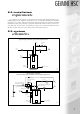
GEMINI HSC 15.0 water connections primary water connections Primary flow and return connections should be made to the calorifier using appropriate sized fittings with a male BSP component that allows for disconnection of the unit. Care must be taken to ensure that connections are watertight to avoid unseen leakage and external corrosion damage to the exterior tank and to avoid water entry into electrical components.
GEMINI HSC 16.0 filling the water heater etc. (contd) 10. Fill the primary side (outer tank) and ensure correct and proper venting via the primary air (manual) air vent located adjacent to the primary flow in connection. Note: failure to properly vent the primary side of the calorifier will result in circulation noise and poor performance of the unit. IMPORTANT OBSERVATIONS Failure to observe the correct sequence of filling (ie. domestic first) may lead to irrepairable damage to the calorifier. 11.
GEMINI HSC 18.0 optional immersion heaters Each Gemini HSC Calorifier can be fitted with an optional immersion heater. The heater element is installed into the primary tank underneath the domestic stainless steel vessel. This ensures thorough heatup of the domestic water and avoids scale build up on the element. The immersion heater will provide a nominal supply of hot water during boiler shutdown. Model Immersion Heater Rating kW Recovery Time ∆t 50°C 60 - i 1.5 3.0 hrs 100 - i 2.2 3.
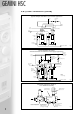
GEMINI HSC 21.0 immersion heater replacement Fig 13. In order to replace the electric immersion heater it is necessary to drain the primary side only, see section 20.1. 1. Electrically isolate the calorifier. 2. Remove immersion heater cover panel models 200-i, 300-i and 500-i or control panel models 60-i, 100-i and 150-i. 3. Disconnect electrical connections from immersion heater (note: some models have additional manual reset high limit stat - not shown). 4.
GEMINI HSC 22.0 internal inspection (secondary) The Gemini HSC i range of calorifiers is designed to allow internal inspection/cleaning access. Fig 14. 10 Fig 15. 11 4 Fig 16. To gain access for internal inspection: 1. Isolate and drain the calorifier as described on in section 20. 2. Disconnect all secondary pipework, stripping away sections of pipework as necessary to allow full access for removal of tube plate and dip tube assembly (10) fig.15. 3.
GEMINI HSC 23.0 optional 3 phase 7.5kW Immersion heater for model 500-i As a factory fitted option, a 7.5kW 3phase, 415V immersion heater is available to provide enhanced electrically heated operation for the model 500i. Note: this option is not available on models 60-i, 100-i, 150-i, 200-i or 300-i. Immersion heater rating . . . . . . . . . . . . .7500W 3 phase 415V Recovery time at 50°C ∆t . . . . . . . . . . .4.7hrs 24.0 to reset limit thermostat (all models) 1. Electrically isolate the calorifier. 2.
GEMINI HSC QW/11/00 A member of the Modular Heating Group Plc 35 Nobel Square, Burnt Mills Industrial Estate, Basildon, Essex SS13 1LT Tel: 01268 591010 Fax: 01268 728202 http://www.modular-heating-group.co.uk This publication is issued subject to alteration or withdrawal without notice. The illustrations and specifications are not binding in detail. All offers and sales are subject to the Company's current terms and conditions of sale.