
Technical data

17
GEMINI HSC
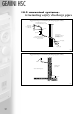
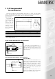
14.0 electrical
connection
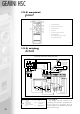
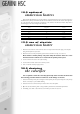
to make electrical connections
Remove 4 no. fixing screws (1) retaining control panel (2).
Carefully rotate control panel (2) to expose electrical connection terminal rail (3). See Fig.11.
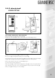
Carefully cut out cable entry aperture (5) on calorifier top cover (4).
Lift up top cover (4), removing first the cleaning access cover panel (9).
Route appropriately sized cables (multi strand flex only) (6) through aperture (5), through cable clamp (8)
and guide cables carefully down through cable tube (7) to terminate at the control panel rear.
Make necessary electrical connections to terminal rail (3) See fig.12.
(see also electrical connection diagram fig.10)
Refit control panel (2) to calorifier using screws (1). Ensure cables (6) are routed correctly with sufficient
slack to allow future easy access to rear of control panel (2) and securely retain cables under clamp (8).
Refit top cover (4) and cleaning access cover panel (9).
1
2
3
2
4
9
5
7
6
8
6
3
Fig 11.
Fig 12.