
Technical data


GEMINI HSC
7
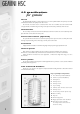
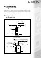
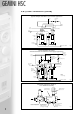
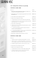
9.0 system
schematics
Cold
Feed
Flow
From
Boiler
Drain at
Low Level
Secondary
Pump
IV IVNRV
3 Way Vent Valve
Return to Boiler
typical single calorifier
unvented-direct-on-mains/boosted supply application
Cold Supply
Pressure Limiting Valve with
Integral Strainer Set 3.5 bar
Core Assembly with
Integral Non-Return Valve
Stop
Valve
Flow
from
Boiler
IVNRV
Tundish
Drain at
Low Level
2 Port Spring
Return
Motorised
Valve
Temperature & Pressure Relief Valve
Set 7.0 bar & 90-95°C
3 Way Vent Valve
Return to Boiler
Secondary
Pump
IV
Expansion Vessel
Expansion Relief Valve
Set 6.0 bar
typical single calorifier open vented application
Open
Vent
IV
8.0 installation
requirements
The calorifiers must be installed to comply with the Water Supply (Water Fittings) Regulations 1999,
Building Regulations, I.E.E. Regulations and the Bye-Laws of the local Water Company. The installation
should also be in accordance with any Local Authority requirements and the recommendations of CP342
Centralised hot water supply, or BS6700 as appropriate. Gemini HSC calorifiers should be positioned on a
level plinth which must be capable of supporting the weight of the calorifier when filled with water.
Allowance should be made for access to the flow, return and electrical connection.
Fig 3.
Fig 4.
Isolation Valve
Balanced Pressure Cold Water Supply