
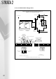
Technical data


25
STRATA2
Table 5
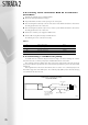
5.7.5 connecting remote fault alarms
The boiler includes a normally open volt free contact for each module, which closes in the event of a
lockout failure. See “Electrical Connection Details” section 5.7.
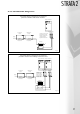
5.8 connecting additional boilers
A second boiler unit does not require an additional RVA 47 manager, as the manager in the first unit is
capable of controlling up to 4 burners. Connect the power supply to the second unit. Install a pair of
screened wires between the PPS connectors of boilers 1 and 2. Observe polarity.
Note: PPS connector = light blue.
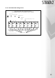
5.8.1 connecting third, fourth, fifth, sixth,
seventh and eighth units
These boilers must have RVA 47 managers. To connect RVA 47 manager in additional boilers; the LPB
terminals in each boiler that includes an RVA 47 manager must be linked, i.e. all left hand LPB terminals must
be linked on to another, and all right hand LPB terminals must be linked one to another. Do not link any left
hand terminal to any right hand terminal. Screened cables required.
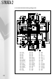
5.8.2 boiler manager RVA 47 installation
procedure (normally factory fitted)
Complete the following steps to install the manager:
● Remove the blank panel to the right of the display panel.
● Unpack the RVA 47 and insert it in the opening of the control panel.
● Place the first wiring harness with 6-pin connector in the bottom of the RVA 47 and click the other end
into the wiring upstand at the rear of the boiler.
● Place the second wiring harness with the 8-pin connector in the top of the RVA 47 and click the other
end into the wiring upstand at the rear of the boiler.
● Connect the boiler power supply (3 pin male connector) to the RVA 47 unit.
● Connect the PPS communication wire (Orange/Grey) to the female plug connected to the (Blue/
Grey) wire.
The following can now be connected as necessary:
SLP DHW pump or 3-way valve Beige
HKP Heating system pump Yellow
PPS Connection to second boiler Blue
LPB Connection to subsequent RVA 47 Mauve
VFO Flow sensor White
SF DHW sensor Clear
AF Outside air sensor or resistor substitute (620 Ω) Black
REO Room unit or thermostat Light blue
H1 Remote enable or (volt free) 0-10 Volt Orange
RFO Return Sensor Clear
* = Compulsory connections. All other connections as necessary.
*
*