MICROMAT EC Wall mounted Ultra High Efficiency Gas Boilers 16/22 24/28 31/36 38/45 Instructions for Usage, Installation & Commissioning
Index Page 4 8 8 10 11 11 11 12 12 13 14 14 15 16 19 22 24 33 33 33 43 44 45 48 50 52 Section 1.0 2.0 3.0 4.0 5.0 6.0 7.0 8.0 9.0 9.1 10.0 11.0 12.0 13.0 14.0 15.0 16.0 16.1 16.2 17.0 18.0 18.1 18.2 18.3 18.4 18.
1.0 user instructions for the micromat boiler Boiler Switch Panel Display ON/Off switch Water pressure guage Menu/Reset Button Summer/Winter and “+” button Engineers Test button and “-” button Before operating the boiler: Check that the boiler has been installed in strict accordance with the instructions contained in this manual. Non compliance with the instructions may result in injury and/or damage to property.
1.0 user instructions for the micromat boiler Description of Boiler Contr ols Controls Menu/Reset Button This button has three functions 1. Resetting of fault conditions: - When the display text is flashing on and off, a boiler fault is indicated. The type of fault is displayed on the screen. Please refer to the fault finding section on page 56 for a description of these faults. The boiler control is reset by pressing the Menu/Reset button once. 2.
1.0 user instructions for the micromat boiler [*5] Set CH Times The central heating on and off times are adjusted using this menu point. There are three ON times and three OFF times per day. There are two sub-menus in this menu. a) Day required b) On and Off times for central heating With the menu item [Set CH Times] displayed, press the menu/reset once and [Monday] appears in the display. One can move between the days using the ‘+’ and/or ‘-’ buttons.
1.0 user instructions for the micromat boiler Engineer s Button Engineers The user will not normally need to use this button. It is used by the service technician to enable measurement of flue emissions even without heat requirement being present. NOTE: This function will not be available if the MICROMAT EC and the heating system have reached their maximum temperatures. If the Engineers button is pressed once then the MICROMAT EC operates with half power. The display shows [Flue Emissi].
2.0 general notes These instructions are intended to assist the installer, commissioning engineer, maintenance engineer and user with the installation, maintenance and usage of MICROMAT EC 16/22, 24/28, 31/36 & 38/45 models gas fired condensing boilers. Please read this manual fully before commencing the installation of the appliance. The MICROMAT EC must only be installed by persons deemed to be competent. This manual must be handed to the appliance user following completion of the installation. 3.
3.0 product description energy saving In addition to the extremely efficient burner and heat exchanger system employed in the MICROMAT EC each appliance includes a modulating speed boiler primary pump. This feature allows the boiler to self-maintain a 20°C ∆t across the heat exchanger, optimising the heat exchanger efficiency and reducing also the electrical consumption of the pump motors.
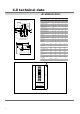
4.0 technical data & dimensions Model underside - models EC16/22, EC24/ 28, EC31/36 & EC38/45H 60 4 60 5 6 7 50 110 60 3 9 100 10 145 40 100 8 145 plan - models EC16/22, EC24/28, EC31/36 & EC38/45H 458 16/22 24/28 31/36 38/45 Nominal Heat Input Nett (max) MICROMAT EC kW 2.9-15.0 3.4-22.0 4.8-29.0 6.4-36.0 Nominal Heat Output 80/60°C kW 2.5-14.3 3.1-21.4 4.5-28.4 6.0-35.1 Nominal Heat Output 50/30°C kW 3.1-15.8 3.6-23.1 5.1-30.7 6.8-38.
5.0 delivery consignment unpacking the boiler The boiler is delivered as a consignment of a carton containing the boiler and associated fittings, plus any other optional ancillary flue or control components in separate cartons. The boiler carton contains • Assembled Boiler • Wall mounting bracket • Fittings bag attached to corner bracket of packaging containing outside air temperature sensor, vent key and hose connection.
8.0 wall mounting 45 458 ∅ 12 165 important 945 165 115 2x35x12 785 The MICROMAT EC boiler mounts to the wall via a wall mounting bracket which interlocks to a rail mounted on the rear of the boiler. The wall mounting bracket should be firmly fixed to the wall using suitable fixings with a countersunk head. The wall mounting bracket positioning detail is shown in fig 1.
9.1 gas conversion The MICROMAT EC is factory fitted for Natural Gas (G20). However the unit can easily be converted to LPG (G31) by using the kit supplied (part no. 251588) and following the instructions below. •Remove cover from boiler •Open the outlet flange joints at the gas combi valve. •On the outlet side of the gas combi valve add the Ø 5.7mm LPG jets from the conversion kit. •Re-tighten the flange joint. Do not forget the O-ring. •Check for Leakage.
10.0 system flow & return connections NOTE: The MICROMAT EC boiler must only be installed on sealed and pressurised systems. The maximum working pressure of the boiler = 3 bar. It is recommended that the final working pressure (hot) of the system does not exceed 2.3 bar. The boiler is equipped with a 22mm flow connection on the left (when looking head on at the boiler) and one return on the right (22mm). fig 3 fig 4 Exhaust (125mm) Air Intake (70mm) Return DHW/Storage Connection (EC...HS & EC...
11.0 condensate connection (contd.) If any part of the condensate pipe is to be run external to the building or is at risk of freezing, then the pipe must be suitably insulated to protect from freezing. If a suitable drain for accepting the condensate is not available nearby to, and below the boiler (e.g.
13.0 flue systems The MICROMAT EC has an excess pressure combustion system that allows the appliance to be exhausted over extended distances using small OD flue components. The flue gas temperature is extremely low (typically the same as the flow water temperature), which allows the use of easy to install PPS (polypropylene) flue pipe and fittings.
13.0 flue systems Flue System Option No No.. 2 tical Balanced F lue System ertical Flue Ver Using this system the air for combustion and the flue products are piped vertically to/from outside the space. The balanced flue may exit through both flat and pitched roofs. Suitable flashings are available for either case. This following components and options are available from RVR Limited: •70/125 concentric roof terminal set, complete with concentric pipes and terminal.
13.0 flue systems Cut Flue Hole Dia 130mm of op ssis e T ha Lin ce C n a pli Ap 70mm Ø Grey PPS Pipe Order Code SBA059 70mm Ø Grey PPS Pipe 250mm long Order Code SBA057 155 170 70mm Ø Grey PPS Pipe 500mm long Order Code SBA058 Flue Products Sampling Tee Order Code SBA052 Cut Flue Hole Dia 130mm 70mm Ø 90° Bend Grey PPS Order Code SBA060 170 MICROMAT EC C L Flue System Option No. 3 Horiz ontal Disc har ge with air ffor or Comb ustion tak en fr om R oom.
14.0 calculating flue resistance The excess pressure available for overcoming the frictional resistance of a flue system is 100 Pa. The table below of flue component resistances will assist the designer in calculating total flue system frictional loss. If the total installed flue system resistance exceeds 100 Pa., then the result will be a reduction in boiler output. Reference to the ‘Effect of Flue System Resistance On Boiler Output”, graphs will assist.
14.
14.0 calculating flue resistanceflue pressure loss Minimum dimensions of flue terminal positions see fig. 7 below D i mensi on Termi nal Posi ti on A B Balanced Flue Room Sealed D i rectly below an openi ng, ai r bri ck, wi ndows etc. Not Recommended Below gutters, soi l pi pes or drai n pi pes Non Room Sealed 300mm 300mm 75mm 75mm 200mm 200mm 200mm But i nstallati on not recommended 200mm But i nstallati on not recommended C Below eaves D Below balconi es or car port roof.
15.0 ventilation requirements single appliances The room or space in which the Micromat EC boiler is installed is required to be ventilated in accordance with BS 5440: Part 2:2000. The following tables must be read to ascertain the amount of ventilation required. Table 1 Room Intallation - Non Room Sealed Flue.
15.
16.0 hydraulic system design • The MICROMAT EC boiler can be operated to serve a heating load in a number of ways: I.Constant flow temperature, with the option to set either high temperature (85°C), medium temperature (75°C) or low temperature (55°C). 2.Direct-on-boiler weather compensated flow temperatures, with adjustable maximum flow temperature. 3.Underfloor heating coils via a VT mixing valve with a maximum flow temperature of 55°C plus a second circuit (eg.
16.0 hydraulic system design System type 1 Typical Typical Single MICROMAT EC boiler installation serving heating only where the boiler’s own in-built circulating pump is used to circulate the water around the system (used only where system index resistance <1 metre). Flow temperature may be fixed/constant or weather variable.
16.0 hydraulic system design System type 2 Typical Single MICROMAT EC boiler installation serving domestic hot water and heating where hot water has priority via a divertor valve. The in-built circulating pump in the boiler is used to circulate the system (used only where system index resistance <1 metre). Flow temperature to hot water is constant and flow temperature to heating may be constant or weather variable.
16.0 hydraulic system design System type 3 Typical Single MICROMAT EC boiler installation serving heating only and using a low velocity mixing header where system index resistance exceeds 1 metre. Flow temperature may be fixed/constant or weather variable. OS Micromat EC boiler C PRO 1 AAV Safety Valve LSV Return from system circuits Condensate IV Flow to system circuits DOC IV IV Strainer DOC Expansion Vessel DOC Low velocity mixing header Max. velocity 0.
16.0 hydraulic system design System type 4 Typical Single MICROMAT EC boiler installation serving heating & domestic hot water. Hot water is priority and is served via a divertor valve and the boiler’s in built circulating pump where index loss through HWS primaries is less than 1 metre. Heating circuit index loss exceeds 1 metre and is served via a low velocity mixing header and a separate pump. Heating flow temperature may be fixed/constant or weather variable.
16.0 hydraulic system design System type 5 Typical Single MICROMAT EC boiler installation serving heating & domestic hot water with hot water priority. Hot water & heating circuits both have index resistance exceeding 1 metre & are served by independent pumps from a low velocity mixing header. Heating flow temperature may be fixed/constant or weather variable.
16.0 hydraulic system design System type 6 Typical Multiple MICROMAT EC installation. Boilers controlled by modulating Kaskade manager which also has the facility to control heating & domestic hot water production. Heating flow temperature may be fixed/constant or weather variable. Hot water has priority. OS C KKM 2 Flow to System Circuits Micromat EC boiler Heating pump 2A. Max Micromat EC boiler Micromat EC boiler FS HWS Primary Pump 2A.
16.0 hydraulic system design System type 7 Typical Single MICROMAT EC boiler installation serving domestic hot water and radiator heating zone and an underfloor coil zone all via a low velocity mixing header. The HWS will always have priority. The 2Nr heating zones may operate independently via 2 Nr separate room units. The 2 Nr heating zones will always be weather compensated but may have differing compensation slopes.
16.0 hydraulic system design System type 8 Typical Single MICROMAT EC boiler installation serving heating and domestic hotwater via a system pump and 2Nr 2Port motorised valves with conventional controls i.e. programmer, room stat & cylinder stat. NOTE: system temperature will be fixed constant and direct-on-boiler weather compensation is not possible.
16.1 water treatment system cleaning The entire system must be thoroughly cleansed and flushed to remove debris, flux residues etc before opening the boiler isolation valves & flooding the boiler. Particular care must be taken where the MICROMAT EC boiler is being retro-fitted into an old/existing system, as system silt or magenite can be very damaging to the new boiler. The system must be filled with clean chemically neutral water. Water hardness must not exceed 3.6 mol/m 3 (=20°dH).
2 1 1 1 2 1 2 1 2 S5 2 S3 1 10 S4 2 RS 232 S1 K5 K5 Flow temperature sensor X10 K6 K6 X12 1 5 10 1 2 not used DHW Thermostat or DHW Temperature sensor Outside temperature sensor RE2132 8 1 PRO1/MRO3 16 6 X16 K14 K3 11 1 9 KO = white K2 = brown K3 = green K4 = grey K5 = orange K6 = blue K7 = red K8 = black 3 6 1 4 2 K18 K12 K9 = violet K12 = yellow/white K13 = brown/white K14 = green/white K17 = blue/white K18 = red/white K19 = black/white K20 = violet/white 6 Fu
L1 PE N Install only one method of external time and room temperature control. If room and stat time switch are required, then do not install RE2132 room unit and vice versa. ** On LPG installations where an additional gas safety shut off valve is required, connect to L1 and N terminals on left side of lower terminal strip. Install only if direct-on-boiler weather compensated flow temperature are required.
*** ** * On LPG installations where an additional gas safety shut off valve is required, connect to L1 and N terminals on left side of lower terminal strip. Install only one method of HWS temperature control. The use of an HWS sensor will allow no time control over hot water production. If timed hot water control is required then do not install an HWS sensor, but install only timeswitch & cylinder thermostat. Install only one method of external time and room temperature control.
** * Supply L1 PE N On LPG installations where an additional gas safety shut off valve is required, connect to L1 and N terminals on left side of lower terminal strip. Install only one method of external time and room temperature control. If room and stat time switch are required, then do not install RE2132 room unit and vice versa. Install only if direct-on-boiler weather compensated flow temperature are required.
*** On LPG installations where an additional gas safety shut off valve is required, connect to L1 and N terminals on left side of lower terminal strip. Install only one method of HWS temperature control. The use of an HWS sensor will allow no time control over hot water production. If timed hot water control is required then do not install an HWS sensor, but install only timeswitch & cylinder thermostat. ** Install only if direct-on-boiler weather compensated flow temperature are required.
*** ** * X3 X16 upper terminal strip = Control sockets on control panel = Weiland Plugs / Sockets On LPG installations where an additional gas safety shut off valve is required, connect to L1 and N terminals on left side of lower terminal strip. Install only one method of HWS temperature control. The use of an HWS sensor will allow no time control over hot water production. If timed hot water control is required then do not install an HWS sensor, but install only timeswitch & cylinder thermostat.
5 N L * Heating Circuit Pump 230V 2A Max PE N L N L Supply PE 230V 9 16 15 11 17 13 20 16 19 15 Alternative External Control Options 18 14 22 18 21 17 19 X2 20 4 22 21 3 2 1 5 X2 GND 7 12 PMW * Modulating Room unit +24V RE2132 * QAW44 optional Remote Sensor PE * HWS Primary Pump 230V 2A Max * - If Required 3 X1 23 26 25 Not Used 24 28 27 R3 10 30 29 1 32 31 34 35 Additional Boilers 33 36 R3 1 6 * Cylinder Stat / HWS Time Switch 1 38 3
*** ** * On LPG installations where an additional gas safety shut off valve is required, connect to L1 and N terminals on left side of lower terminal strip. Install only one method of HWS temperature control. The use of an HWS sensor will allow no time control over hot water production. If timed hot water control is required then do not install an HWS sensor, but install only timeswitch & cylinder thermostat. Install only one method of external time and room temperature control.
On LPG installations where an additional gas safety shut off valve is required, connect to L1 and N terminals on left side of lower terminal strip. Install only one method of external time and room temperature control. If room and stat time switch are required, then do not install RE2132 room unit and vice versa. ** 230V L1 PE N Supply Install only if direct-on-boiler weather compensated flow temperature are required.
17.0 electrical connections Remote Fault Indication The MICROMAT EC boiler includes a built in fault alarm relay with volt free contacts for interface with, if required a remote alarm indicator. The volt free contacts within the boiler control panel will close in the event that the boiler goes to a fault resulting in boiler lockout. The volt free contacts indicate “common alarm” upon closing. The actual fault description will be displayed upon the LCD screen of the boiler.
18.1 pre-commissioning checks a) Ensure system has been thoroughly cleansed and flushed, any strainers have been cleaned and that the appropriate water treatment has been added to the system to prevent corrosion, scale formation etc. b) Ensure the system and boiler has been properly and fully flooded and vented of air and the cold fill pressure at the boiler is at a minimum 0.
18.2 installation codes Weather compensated control without DHW sensor or with DHW control via thermostat and three way valve. Function Number Low Temperature heating 1 with RE2132 Room Unit Weather Compensation without mixing circuit.
18.
18.2 installation codes Room temperature controlled (without weather compensation) with DHW sensor and pumped DHW circuit.
18.3 first firing Notes The MICROMAT EC boiler has a single heat exchange and burner assembly. There is one gas valve serving the assembly. a) Ensure gas & electricity supplies are turned on to the appliance. Menu/Reset Display Button ON/Off switch b) Switch on the boiler at the on/off switch. (See figure to the right) The appliance will purge the combustion chamber with air from the burner fan and then will pulse the pumps on/off (deaerating).
18.3 first firing h)Check CO2% of heat exchanger and adjust as necessary screw (4) Q max of right hand valve, to obtain required value. (See table I) NOTE: Adjustment of either (3) Q min or (4) Q max will affect the other adjustment to a lesser or greater extent. Following either adjustment of (3) or (4) check the effect on the setting of the other adjustment and correct as necessary. i)Remove analyser from upper heat exchanger and refit cap/plug to test point.
18.4 commissioning -pop-up menu & weather compensation Explanation of the [install] pop up menu Menu Point [1] [2] [3] [4] [5] [6] [7] [8] [9] [10] [11] [12] [13] [14] Parameter Curv 20C CH Curv -1C CH Pump min Pump max Curv 20C MV Service in Pump Continue ECO+ Postrun HW Postrun CH Min Power Max Power Function Nr Back Minimum Maximum Default value Adjustment Unit -20 20 0 1 0C 0 -20 20 0 1 C 35 Pump max 35 1% Pump min.
18.4 commissioning -pop-up menu & weather compensation [3] The minimum pump revolution setting [pump min] To set the minimum pump revolutions select menu item [3] and press the ‘reset’ key to confirm. The value may then be changed by using the ‘+’ and ‘-’ keys. Confirm the selection by pressing the ‘menu’ key. [4] The maximum pump revolutions setting [pump max] To set the maximum pump revolutions select menu item [4] and press the ‘reset’ key to confirm.
18.5 commissioning the status indicator Overview of fan revolutions per minute Boiler type EC 11/22 EC 15/22 EC 23/28 EC 31/36 EC 40 H Boiler Absolute Max HK?? Start Revs Min. rev/min Max. Rev/min Rev/min Rev/min [%] 900 6000 2200 3000 100 900 6000 2200 4080 100 900 6000 2200 4680 100 900 6000 2200 4860 100 1260 6300 2200 6300 100 Min. Boiler standard Rev/min [%] of max. HC 1380 46 1380 33 1380 29 1380 28 1380 22 Min. Boiler absolute Rev/min [%] of max.
18.6 setting domestic hot water temperature A) With HWS sensor in/on calorifier Press and hold the menu/reset button on the boiler conbtrol panel for over 3 seconds. Next press the ‘+’ key until [temp DHW] appears on the display. Press the menu/reset button to enter adjustment mode. Press the ‘+’ or ‘-’ key to adjust the setpoint. The maximum temperature temperature setting is 60°C.
20.1 inspection a) Ask the user about any problems with the boiler unit or any other comments. b) Check the water pressure of the installation. c) Remove the casing of the unit and inspect all pipes and connections for water leaks. d) Inspect the top of the casing and/or the top of the upper heat exchanger for water leaks or signs of water from the flue air supply tube. e) Open the siphon cleaning rinsing point at the base of the unit.
at k) If dirt has deposited on the fan blades, each blade must be carefully cleaned, until the blade material is visible again. If this is not done evenly the fan will not rotate properly and be out of balance.
21.0 screen display diagnosis of faults 2.1 Screen display The control panel of the MICROMAT EC boiler has an LCD screen, displaying two lines of data. This screen provides information about the operation of the appliance; it shows operation messages (non flashing) and fault messages (flashing display). The first line contains text information about the status of the unit.
21.1 screen display diagnosis of faults STATUS MESSAGES (FLASHING DISPLAY) INDICATING A FAULT A flashing display indicates a fault and that the boiler has shutdown (lockout). The boiler will not attempt to operate until the red’ reset button is pressed. Any repetitive flashing fault message should be investigated, the cause found and corrective action taken. For each flashing display message there is a possible cause, see list of cause numbers following the flashing status’ list.
21.1 Screen display/ Diagnosis of faults (contd) Gas valve Connection to gas valve interrupted 16,26,28,29,31,33 Soft fault Error in software in the control 29 Reset button There is a fault with the reset button 29,31,34 Eeprom There is a fault in the EEPROM in the control 29 21.2 (possible) causes of fault & corrective action CAUSE No.
21.
For further information please contact: RVR Limited Kenmare Co Kerry Ireland Tel: +353 64 41344 Fax: +353 64 41511 email: man@rvr.