
Technical data


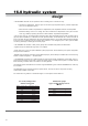
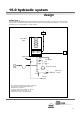
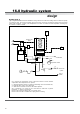
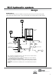
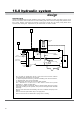
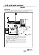
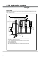
Table Of Contents
- User Instructions for the Micromat boiler
- Product Description
- Technical Data
- Delivery Consignment / Unpacking the boiler
- Boiler location
- Installation Clearances
- Wall Mounting
- Gas Connection
- Gas Conversion
- System Flow & Return connections
- Condensate Connection
- Flue / Combustion Air connection
- Flue Systems
- Calculating Flue Resistance
- Ventilation requirements single appliances
- Hydraulic System Design
- System type 1
- System type 2
- System type 3
- System type 4
- System type 5
- System type 6
- System type 7
- System type 8
- Water Treatment
- Soldering Flux
- Electrical Connection
- System Type 1
- System Type 2
- System Type 3
- System Type 4
- System Type 5
- System Type 6
- System Type 7
- System Type 8
- Commissioning The Micromat EC
- Installation Codes
- First Firing
- Pop Up Menu
- Setting DHW Temperature
- Servicing
- Screen Display Diagnosis of Faults

24
• The MICROMAT EC boiler can be operated to serve a heating load in a number of ways:
I.Constant flow temperature, with the option to set either high temperature (85°C), medium temperature
(75°C) or low temperature (55°C).
2.Direct-on-boiler weather compensated flow temperatures, with adjustable maximum flow temperature.
3.Underfloor heating coils via a VT mixing valve with a maximum flow temperature of 55°C plus a second
circuit (eg. radiators) operating with direct-on-boiler weather compensated temperatures.
• Flow to return drop (∆t). The microprocessor controls monitor return temperature and the facility to dictate a set ∆t
(by pump speed modulation) is a standard and most important feature and will maintain the ∆t across the boiler at
20°C, as the lower the return temperature, the higher the operating efficiency. HT and MT systems should be designed
for ∆t 20°C and LT (underfloor coils via a mixing valve) systems ∆t 10°C. Designing for a ∆t 20°C gives the added
cost saving advantage of smaller pipe sizes and pumps.
• The MICROMAT EC includes ‘in built’ primary pumps with a residual head pressure as listed below.
• Appliances may be installed as single units or in multiples.
• Single units may or may not require additional system pumps which will be dictated by the system configuration
and by the index resistance.
• Multiple units (and single units which require additional pumps), should always be installed with a low loss mixing
header or similar arrangement – see table below.
• The MICROMAT EC boiler has in built domestic hot water (remote stored) temperature control ability, and if re-
quired, the in built pumps may be used to provide the primary flow to a nearby indirect cylinder or calorifier with the
boiler controlling a diverter valve in the main flow or return pipework.
The following system schematics show a number of typical installation types to which the MICROMAT EC boiler may
be connected.
The MICROMAT EC is not limited to just the systems shown, and may be used in conjunction with many
commercially available control items.
For further advice or guidance on schematic designs or control options contact RVR Ltd.
16.0 hydraulic system
design
WkrewoPrelioBngiseD ∆ C°02t
54otpUmm04
57mm05
001mm56
021mm56
051mm08
002mm08
052mm001
072mm001
003mm001
043mm001
morfdetaluclacdnaepipleetsotrefersretemaiDebuT
4CediuGESBIC
low velocity mixing header
diameter sizing guide
ledoMrelioBcwserteMerusserP
22/611
82/421
63/131
54/831
Inbuilt boiler pumps
approx residual head pressure at
∆∆
∆∆
∆t 20°C