
Technical data
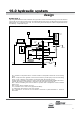
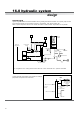
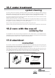
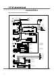
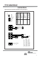
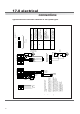
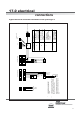
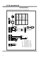
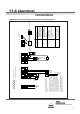
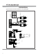
Table Of Contents
- User Instructions for the Micromat boiler
- Product Description
- Technical Data
- Delivery Consignment / Unpacking the boiler
- Boiler location
- Installation Clearances
- Wall Mounting
- Gas Connection
- Gas Conversion
- System Flow & Return connections
- Condensate Connection
- Flue / Combustion Air connection
- Flue Systems
- Calculating Flue Resistance
- Ventilation requirements single appliances
- Hydraulic System Design
- System type 1
- System type 2
- System type 3
- System type 4
- System type 5
- System type 6
- System type 7
- System type 8
- Water Treatment
- Soldering Flux
- Electrical Connection
- System Type 1
- System Type 2
- System Type 3
- System Type 4
- System Type 5
- System Type 6
- System Type 7
- System Type 8
- Commissioning The Micromat EC
- Installation Codes
- First Firing
- Pop Up Menu
- Setting DHW Temperature
- Servicing
- Screen Display Diagnosis of Faults
Energy Technology
Ltd.
39
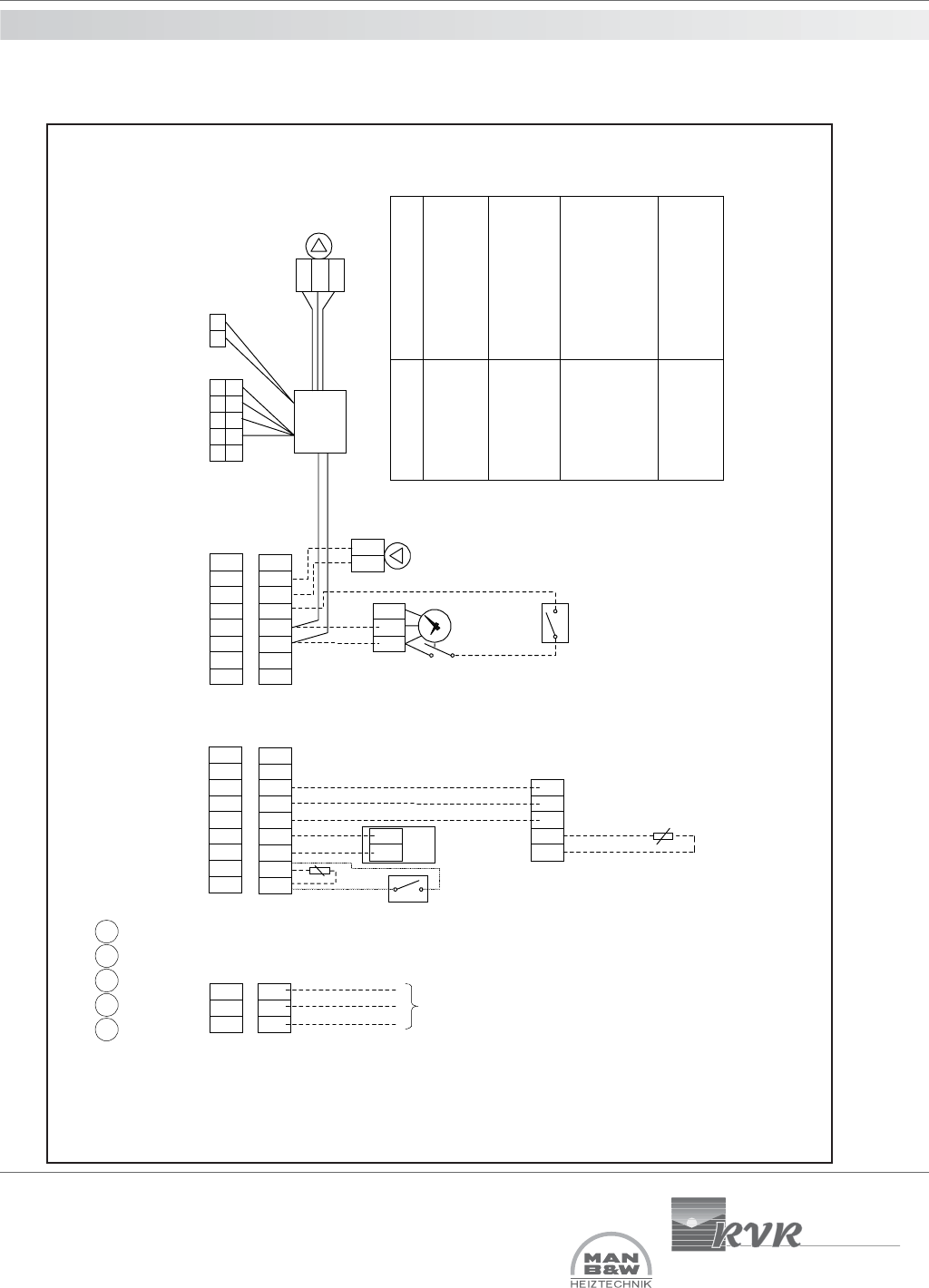
17.0 electrical
connections
Typical electrical connection schematic to suit system type 5
PRO 1
L
PE
N
Heating Pump 2A Max
Installation code
Outside sensor
installed. Room stat &
time switch installed.
1 3 4 5 6
= Weiland Plugs / Sockets
X16X3
= Control sockets on control panel
No outside sensor.
Room stat & time switch
installed.
Outside sensor
installed. RE2132
modulating room unit
installed.
No outside sensor.
RE2132 modulating
room unit installed.
Install only if direct-on-boiler weather
compensated flow temperature are
required.
Install only one method of external time and
room temperature control. If room and stat
time switch are required, then do not install
RE2132 room unit and vice versa.
*
**
X3
10
5
6
1
21
upper terminal strip
L1
PE
N
L1
N
L2
Supply
230V
Room Thermostat
And Time Switch
**
3
4
R1
R2
R3
1 2
O S
4 3 2 5 1
* Outside
Air Sensor
RE2132
Modulating
Room unit
**
QAW44
optional
Remote Sensor
GND
PMW
+24V
1
2
5
6
2 pin plug on X4
L1
N
L1
N
6
23
3
20
lower terminal strip
HWS
sensor
cylinder
thermostat
***
X16
L
N
On LPG installations where an additional gas
safety shut off valve is required, connect to L1
and N terminals on left side of lower terminal
strip.
Install only one method of HWS temperature
control. The use of an HWS sensor will allow
no time control over hot water production.
If timed hot water control is required then do
not install an HWS sensor, but install only
timeswitch & cylinder thermostat.
***
Description